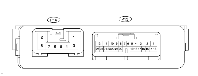
Disconnect the 1C, 1J, 1L, 1K, 1P, B6, B7 and B9 J/B connectors.
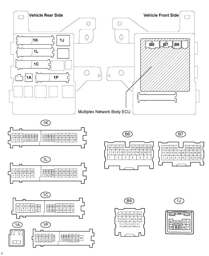
Measure the voltage and resistance according to the value(s) in the table below.
- Standard:
Symbols
(Terminal No.)Wiring Color Terminal Description Condition Specified Condition BECU (1L-7) - Body ground W-L - Body ground +B (BECU) power supply Always 10 to 14 V BECU (1C-24) - Body ground W-L - Body ground +B (BECU) power supply Always 10 to 14 V ALTB (1C-30) - Body ground B - Body ground +B (power system, generator system) power supply Always 10 to 14 V KSW (B6-21) - Body ground L-B - Body ground Key unlock warning switch input No key in ignition key cylinder →
Key inserted10 kΩ or higher →
Below 1 ΩGND1 (1L-16) - Body ground W-B - Body ground Ground Always Below 1 Ω GND2 (1K-17) - Body ground W-B - Body ground Ground Always Below 1 Ω L1 (1J-3) - Body ground R-Y - Body ground Passenger side door control switch LOCK input Passenger door control switch
OFF → LOCK10 kΩ or higher →
Below 1 ΩUL1 (1J-4) - Body ground G - Body ground Passenger side door control switch UNLOCK input Passenger door control switch
OFF → UNLOCK10 kΩ or higher →
Below 1 ΩL1 (1K-25) - Body ground R-Y - Body ground Passenger side door control switch LOCK input Passenger door control switch
OFF → LOCK10 kΩ or higher →
Below 1 ΩUL1 (1K-22) - Body ground G - Body ground Passenger side door control switch UNLOCK input Passenger door control switch
OFF → UNLOCK10 kΩ or higher →
Below 1 ΩL2 (1K-26) - Body ground LG - Body ground Driver side door key-linked LOCK input Driver side door key cylinder OFF → LOCK 10 kΩ or higher →
Below 1 ΩL2 (1J-5) - Body ground LG - Body ground Passenger side door key-linked LOCK input Passenger side door key cylinder OFF → LOCK 10 kΩ or higher →
Below 1 ΩUL3 (B9-8) - Body ground L - Body ground Driver side door key-linked UNLOCK input Driver side door key cylinder OFF → UNLOCK 10 kΩ or higher →
Below 1 ΩUL2 (B7-4) - Body ground L-Y - Body ground Passenger side door key-linked LOCK input Passenger side door key cylinder OFF → UNLOCK 10 kΩ or higher →
Below 1 ΩDCTY (B9-14) - Body ground R-Y - Body ground Driver side door courtesy switch input Driver door
CLOSED → OPEN10 kΩ or higher →
Below 1 ΩPCTY (B7-23) - Body ground R-Y - Body ground Passenger side door courtesy switch input Passenger door
CLOSED → OPEN10 kΩ or higher →
Below 1 ΩLCTY (1P-19) - Body ground GR - Body ground Rear left door courtesy switch input Rear left door
CLOSED → OPEN10 kΩ or higher →
Below 1 ΩRCTY (B9-16) - Body ground R-W - Body ground Rear right door courtesy switch input Rear right door
CLOSED → OPEN10 kΩ or higher →
Below 1 ΩBCTY (B7-25) - Body ground G-W - Body ground Back door courtesy switch input Back door CLOSED → OPEN 10 kΩ or higher →
Below 1 ΩBDSU (B7-3)*1 - Body ground G-B - Body ground Back door opener switch (outside handle switch) input Back door opener switch OFF → ON 10 kΩ or higher →
Below 1 Ω
- HINT:
- If the result is not as specified, there may be a malfunction on the wire harness side.
-
*1: w/o Power back door
Reconnect the J/B and ECU connectors and measure the voltage according to the value(s) in the table below.
- Standard voltage:
Symbols
(Terminal No.)Wiring Color Terminal Description Condition Specified Condition IG (1A-1) - Body ground W - Body ground Ignition power supply Ignition switch
OFF → ON10 to 14 V → Below 1 V ACT+ (1K-2) - Body ground L-R - Body ground Door lock motor LOCK drive output (Driver door) Door control switch (Master switch or passenger side switch) or driver side door key cylinder
OFF →
LOCK →
OFFBelow 1 V →
10 to 14 V →
Below 1 VACT+ (1J-1) - Body ground L-R - Body ground Door lock motor LOCK drive output (Passenger door) Door control switch (Master switch or passenger side switch) or driver side door key cylinder
OFF →
LOCK →
OFFBelow 1 V →
10 to 14 V →
Below 1 VACT+ (1P-17) - Body ground L-R - Body ground Door lock motor LOCK drive output (Rear left door) Door control switch (Master switch or passenger side switch) or driver side door key cylinder
OFF →
LOCK →
OFFBelow 1 V →
10 to 14 V →
Below 1 VTR+ (B6-1)*1 - Body ground L-B - Body ground Door lock motor LOCK drive output (Back door) Door control switch (Master switch or passenger side switch) or driver side door key cylinder
OFF →
LOCK →
OFFBelow 1 V →
10 to 14 V →
Below 1 VACTD (B9-4) - Body ground W-R - Body ground Door lock motor UNLOCK drive output (Driver door) Door control switch (Master switch or passenger side switch) or driver side door key cylinder
OFF →
UNLOCK →
OFFBelow 1 V →
10 to 14 V →
Below 1 VACT- (1J-2) - Body ground L-B - Body ground Door lock motor UNLOCK drive output (Passenger door) Door control switch (Master switch or passenger side switch) or driver side door key cylinder
OFF →
UNLOCK →
OFFBelow 1 V →
10 to 14 V →
Below 1 VACT- (1P-6) - Body ground L-B - Body ground Door lock motor UNLOCK drive output (Rear left door) Door control switch (Master switch or passenger side switch) or driver side door key cylinder
OFF →
UNLOCK →
OFFBelow 1 V →
10 to 14 V →
Below 1 VLSWD (B9-7) - Body ground BR-R - Body ground Driver side door lock position switch Driver side door UNLOCK → LOCK Below 1 V →
10 to 14 V (or pulse generation)LSWP (B7-27) - Body ground Y - Body ground Passenger side door lock position switch input Passenger door
UNLOCK →
LOCKBelow 1 V →
10 to 14 V (or pulse generation)LSWL (1P-5) - Body ground L-R - Body ground Rear left door lock position switch input Rear left door
UNLOCK →
LOCKBelow 1 V →
10 to 14 V (or pulse generation)LSWR (B7-5) - Body ground L-R - Body ground Rear right door lock position switch input Rear right door
UNLOCK →
LOCKBelow 1 V →
10 to 14 V (or pulse generation)
- HINT:
-
*1: w/o Power Back Door
- Use an oscilloscope to check the output voltages of terminals LSWD, LSWP, LSWL and LSWR.
- If the result is not as specified, the J/B (body ECU) may have a malfunction.