Home › BODY › SEAT › FRONT POWER SEAT CONTROL SYSTEM

FRONT POWER SEAT CONTROL SYSTEM > TERMINALS OF ECU

for Preparation Click here


POSITION CONTROL ECU AND SWITCH ASSEMBLY (POWER SEAT CONTROL SWITCH AND ECU)


  1. Disconnect the P58 and P59 connectors.


    B066387E12

  2. Check the voltage of each terminal of the wire harness side connectors.

    Symbols (Terminal No.)
    Wiring Color
    Terminal Description
    Condition
    Specified Condition
    IG (P59-4) - GND (P58-1)
    Y - W-B
    Ignition switch
    Ignition switch off → ignition switch on
    Below 1 V → 10 to 14 V
    SYSB (P59-8) - GND (P58-1)
    W-L - W-B
    Power source
    Always
    10 to 14 V
    +B (P58-5) - GND (P58-1)
    V - W-B
    Battery
    Always
    10 to 14 V
    If the result is not as specified, there may be a malfunction in the wire harness side.

  3. Check the resistance of each terminal of the wire harness side connectors.

    Symbols (Terminal No.)
    Wiring Color
    Terminal Description
    Condition
    Specified Condition
    GND (P58-1) - Body ground
    W-B - Body ground
    Ground
    Always
    Below 1 Ω
    If the result is not as specified, there may be a malfunction in the wire harness side.

  4. Reconnect the P58 and P59 connectors.

  5. Check the voltage of each terminal of the connectors.

    Symbols (Terminal No.)
    Wiring Color
    Terminal Description
    Condition
    Specified Condition
    MPX1 (P59-1) - GND (P58-1)
    R-L - W-B
    Multiplex communication signal circuit
    Ignition switch on
    Pulse generation
    SLD+ (P58-2) - GND (P58-1)
    L - W-B
    Sliding motor signal (Forward)
    Seat moving forward using sliding switch → Other conditions
    10 to 14 V → Below 1 V
    SLD- (P58-3) - GND (P58-1)
    L-B - W-B
    Sliding motor signal (Rearward)
    Seat moving rearward using sliding switch → Other conditions
    10 to 14 V → Below 1 V
    FRV- (P58-4) - GND (P58-1)
    R - W-B
    Front vertical motor signal (Downward)
    Seat cushion front portion lowering using front vertical switch → Other conditions
    10 to 14 V → Below 1 V
    FRV+ (P58-6) - GND (P58-1)
    L-Y - W-B
    Front vertical motor signal (Upward)
    Seat cushion front portion rising using front vertical switch → Other conditions
    10 to 14 V → Below 1 V
    LFT+ (P58-7) - GND (P58-1)
    Y-G - W-B
    Lifter motor signal (Upward)
    Seat rising using lifter switch → Other conditions
    10 to 14 V → Below 1 V
    RCL+ (P58-8) - GND (P58-1)
    R-G - W-B
    Reclining motor signal (Forward)
    Seatback moving forward using reclining switch → Other conditions
    10 to 14 V → Below 1 V
    LFT- (P58-9) - GND (P58-1)
    Y - W-B
    Lifter motor signal (Downward)
    Seat lowering using lifter switch → Other conditions
    10 to 14 V → Below 1 V
    RCL- (P58-10) - GND (P58-1)
    R-B - W-B
    Reclining motor signal (Rearward)
    Seatback moving rearward using reclining switch → Other conditions
    10 to 14 V → Below 1 V
    If the result is not as specified, the position control ECU and switch assembly may be malfunctioning.


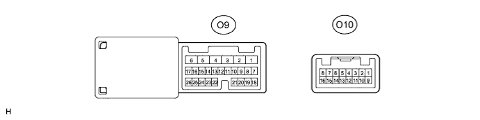
OUTER MIRROR CONTROL ECU LH


  1. Disconnect the outer mirror control ECU LH connector.


    B120940E02

  2. Check the voltage of each terminal of the wire harness side connectors.

    Symbols (Terminal No.)
    Wiring Color
    Terminal Description
    Condition
    Specified Condition
    CPUB (O9-4) - GND (O9-1)
    W-L - W-B
    Power source
    Always
    10 to 14 V
    BDR (O9-6) - GND (O9-1)
    R-L - W-B
    Power window motor power source
    Always
    10 to 14 V
    SIG (O9-3) - GND (O9-1)
    B-R - W-B
    Ignition switch signal
    Ignition switch off → ignition switch on
    Below 1 V → 10 to 14 V
    If the result is not as specified, there may be a malfunction in the wire harness side.

  3. Check the resistance of each terminal of the wire harness side connector.

    Symbols (Terminal No.)
    Wiring Color
    Terminal Description
    Condition
    Specified Condition
    GND (O9-1) - Body ground
    W-B - Body ground
    Ground
    Always
    Below 1 Ω
    If the result is not as specified, there may be a malfunction in the wire harness side.

  4. Reconnect the outer mirror control ECU LH connector.

  5. Check the voltage of each terminal of the connectors.

    Symbols (Terminal No.)
    Wiring Color
    Terminal Description
    Condition
    Specified Condition
    MM (O9-25) - GND (O9-1)
    W-R - W-B
    SET switch signal
    SET switch is not pushed → pushed
    10 to 14 V → Below 1 V
    M1 (O9-22) - GND (O9-1)
    B-W - W-B
    SW1 switch signal
    SW1 switch is not pushed → pushed
    10 to 14 V → Below 1 V
    M2 (O9-23) - GND (O9-1)
    V - W-B
    SW2 switch signal
    SW2 switch is not pushed → pushed
    10 to 14 V → Below 1 V
    If the result is not as specified, the outer mirror control ECU LH may be malfunctioning.