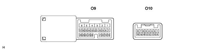
POWER MIRROR CONTROL SYSTEM (w/ Memory) > TERMINALS OF ECU |
| CHECK OUTER MIRROR CONTROL ECU LH |
Disconnect the O9 and O10 connectors.
Measure the voltage and resistance according to the value(s) in the table below.
| Symbols (Terminal No.) | Wiring Color | Terminal Description | Condition | Specified Condition |
| SIG (O9-3) - Body ground | B-R - Body ground | Ignition power supply | Ignition switch OFF → ON | Below 1 V → 10 to 14 V |
| CPUB (O9-4) - Body ground | W-L - Body ground | +B power supply | Always | 10 to 14 V |
| BDR (O9-6) - Body ground | R-L - Body ground | +B power supply | Always | 10 to 14 V |
| Symbols (Terminal No.) | Wiring Color | Terminal Description | Condition | Specified Condition |
| GND (O9-1) - Body ground | W-B - Body ground | Ground | Always | Below 1 Ω |
| SEL1 (O9-21) - Body ground | W-B - Body ground | Ground | Always | Below 1 Ω |
| MPX1 (O9-8) - Body ground | R-L - Body ground | Multiplex communication line | Always | 10 kΩ or higher |
| M1 (O9-22) - Body ground | B-W - Body ground | Memory switch SET1 signal | Memory switch SET1 FREE → PUSHED | 10 kΩ or higher → Below 1 Ω |
| M2 (O9-23) - Body ground | V - Body ground | Memory switch SET2 signal | Memory switch SET2 FREE → PUSHED | 10 kΩ or higher → Below 1 Ω |
| MM (O9-25) - Body ground | W-R - Body ground | Memory switch MEMORY signal | Memory switch MEMORY FREE → PUSHED | 10 kΩ or higher → Below 1 Ω |
Reconnect the O9 and O10 connectors.
Measure the voltage according to the value(s) in the table below.
| Symbols (Terminal No.) | Wiring Color | Terminal Description | Condition | Specified Condition |
| DMVR (O10-1) - Body ground | LG - Body ground | Outer mirror switch signal (Up or Right) | Ignition switch on (IG), Left/Right adjustment switch L side, Mirror switch OFF→ UP or Right | Below 1 V → 10 to 14 V |
| DVC (O10-5) - DE2 (O10-14) | Y - GR | Power source for mirror position sensor | Ignition switch OFF → ON | Below 1 V → 1 to 5 V |
| VSSR (O10-6) - Body ground | G - Body ground | Vertical direction position signal | Ignition switch on, Left/Right adjustment switch L side, Mirror switch uppermost position → lowermost position | Below 1 V → 1 to 3V |
| DMHR (O10-9) - Body ground | P - Body ground | Outer mirror switch signal (Left or Down) | Ignition switch on, Left/Right adjustment switch L side, Mirror switch OFF→ LEFT or DOWN | Below 1 V → 10 to 14 V |
| DM+R (O10-10) - Body ground | O - Body ground | Outer mirror switch signal (Right or Down) | Ignition switch on, Left/Right adjustment switch L side, Mirror switch OFF→ RIGHT or DOWN | Below 1 V → 10 to 14 V |
| HSSR (O10-13) - Body ground | L - Body ground | Horizontal direction position signal | Ignition switch on, Left/Right adjustment switch L side, Mirror switch innermost position → outermost position | Below 1 V → 1 to 3 V |
| LP (O10-2) - Body ground | B-R - Body ground | Puddle light signal | Receive the door UNLOCK signal | 10 to 14 V |
| CYL (O10-12) - CTYB (O10-4) | R-W - R | Front courtesy light LH signal | Each door CLOSED → OPEN | 10 to 14 V |
| CHECK OUTER MIRROR CONTROL ECU RH |
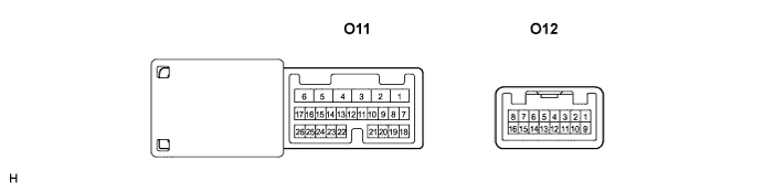
Disconnect the O11 and O12 connectors.
Measure the voltage and resistance according to the value(s) in the table below.
| Symbols (Terminal No.) | Wiring Color | Terminal Description | Condition | Specified Condition |
| SIG (O11-3) - Body ground | B-R - Body ground | Ignition power supply | Ignition switch OFF → ON | Below 1 V → 10 to 14 V |
| CPUB (O11-4) - Body ground | W-L - Body ground | +B power supply | Always | 10 to 14 V |
| BDR (O11-6) - Body ground | R-L - Body ground | +B power supply | Always | 10 to 14 V |
| Symbols (Terminal No.) | Wiring Color | Terminal Description | Condition | Specified Condition |
| GND (O11-1) - Body ground | W-B - Body ground | Ground | Always | Below 1 Ω |
| MPX1 (O11-8) - Body ground | R-L - Body ground | Multiplex communication line | Always | 10 kΩ or higher |
Reconnect the O11 and O12 connectors.
Measure the voltage according to the value(s) in the table below.
| Symbols (Terminal No.) | Wiring Color | Terminal Description | Condition | Specified Condition |
| PMVR (O12-1) - Body ground | LG - Body ground | Outer mirror switch signal (Up or Right) | Ignition switch on, Left/Right adjustment switch R side, Mirror switch OFF→ UP or Right | Below 1 V → 10 to 14 V |
| PVC (O12-5) - PE2 (O12-14) | Y - GR | Power source for mirror position sensor | Ignition switch OFF → ON | Below 1 V → 1 to 5 V |
| VSSR (O12-6) - Body ground | G - Body ground | Vertical direction position signal | Ignition switch on), Left/Right adjustment switch R side, Mirror switch uppermost position → lowermost position | Below 1 V → 1 to 3V |
| PMHR (O12-9) - Body ground | P - Body ground | Outer mirror switch signal (Left or Down) | Ignition switch on, Left/Right adjustment switch R side, Mirror switch OFF→ LEFT or DOWN | Below 1 V → 10 to 14 V |
| PM+R (O12-10) - Body ground | O - Body ground | Outer mirror switch signal (Right or Down) | Ignition switch on, Left/Right adjustment switch R side, Mirror switch OFF→ RIGHT or DOWN | Below 1 V → 10 to 14 V |
| HSSR (O12-13) - Body ground | L - Body ground | Horizontal direction position signal | Ignition switch on, Left/Right adjustment switch R side, Mirror switch innermost position → outermost position | Below 1 V → 1 to 3 V |
| LP (O12-2) - Body ground | B-R - Body ground | Puddle light signal | Receive the door UNLOCK signal | 10 to 14 V |
| CYL (O12-12) - CTYB (O12-4) | R-G - R | Front courtesy light RH signal | Each door CLOSED → OPEN | 10 to 14 V |