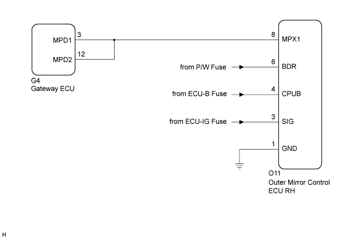
DTC B1208 Passenger Side Outer Mirror ECU |
| DTC No. | DTC Detecting Condition | Trouble Area |
| B1208 | Passenger side outer mirror ECU communication stops |
|
| 1.CHECK HARNESS AND CONNECTOR (OUTER MIRROR CONTROL ECU RH - BATTERY) |
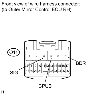 |
Disconnect the O11 ECU connector.
Measure the voltage according to the value(s) in the table below.
| Tester Connection | Connection | Specified Connection |
| O11-3 (SIG) - Body ground | Ignition switch: ON | 11 to 14 V |
| O11-4 (CPUB) - Body ground | Always | 11 to 14 V |
| O11-6 (BDR) - Body ground | Always | 11 to 14 V |
|
| ||||
| OK | |
 |
| 2.CHECK HARNESS AND CONNECTOR (OUTER MIRROR CONTROL ECU RH - GROUND) |
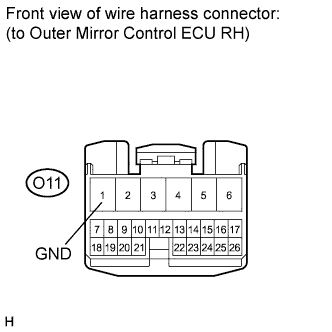 |
Measure the resistance according to the value(s) in the table below.
| Tester Connection | Connection | Specified Connection |
| O11-1 (GND) - Body ground | Always | Below 1 Ω |
|
| ||||
| OK | |
|
| 3.CHECK COMMUNICATION LINE |
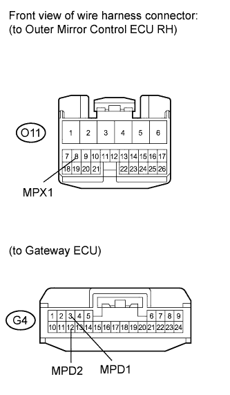 |
Disconnect the G4 ECU connector.
Measure the resistance according to the value(s) in the table below.
| Tester Connection | Connection | Specified Connection |
| O11-8 (MPX1) - G4-3 (MPD1) | Always | Below 1 Ω |
| O11-8 (MPX1) - G4-12 (MPD2) | Always | Below 1 Ω |
| Result | Proceed to |
| Both are OK | A |
| One is OK | B |
| Both are NG | C |
|
| ||||
|
| ||||
| A | ||
 | ||
| ||
