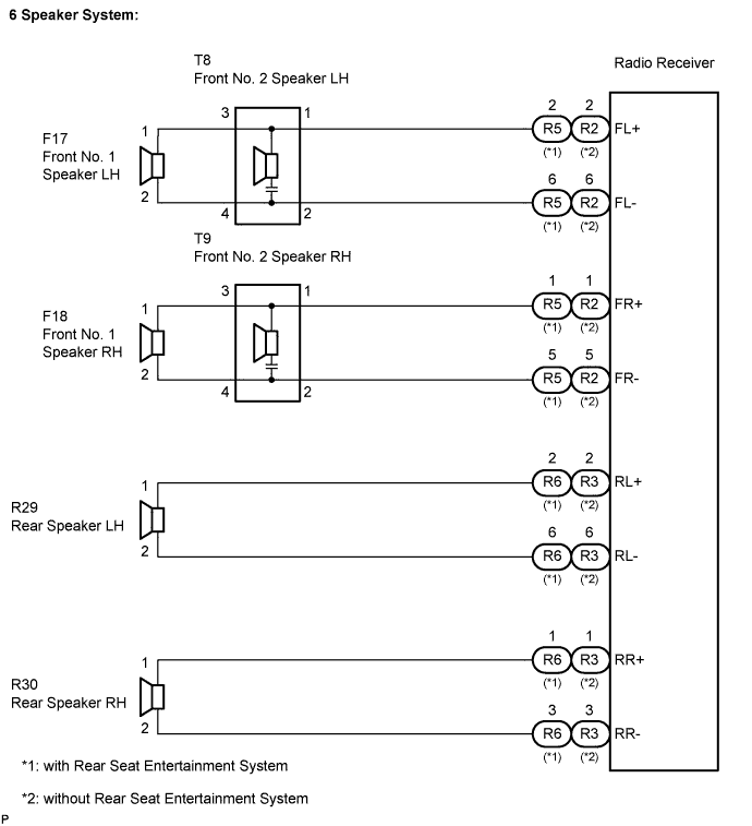
AUDIO AND VISUAL SYSTEM > Speaker Circuit |
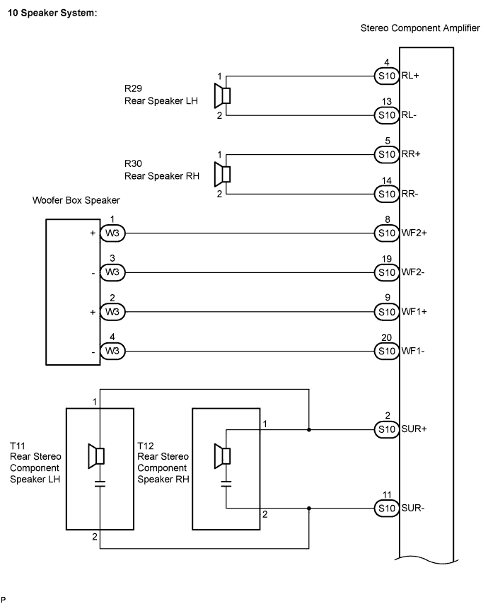
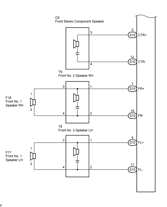
| 1.CHECK HARNESS AND CONNECTOR |
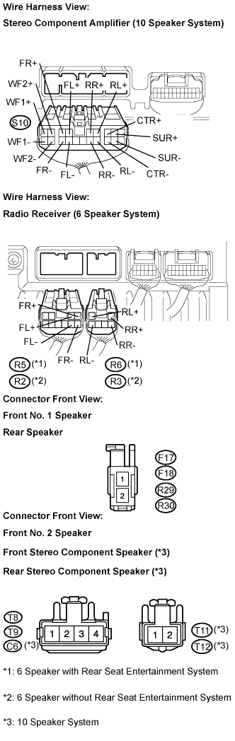 |
Disconnect the connectors shown in the illustration from the stereo component amplifier or radio receiver and speakers.
10 Speaker System:
Measure the resistance between each of the front No. 2 speakers and the stereo component amplifier to check for an open circuit in the wire harness.
6 Speaker System:
Measure the resistance between each of the front No. 2 speakers and the radio receiver to check for an open circuit in the wire harness.
Measure the resistance between each of the front No. 2 speakers and each of the front No. 1 speakers to check for an open circuit in the wire harness.
10 Speaker System:
Measure the resistance between each of the rear speakers and the stereo component amplifier to check for an open circuit in the wire harness.
6 Speaker System:
Measure the resistance between each of the rear speakers and the radio receiver to check for an open circuit in the wire harness.
10 Speaker System:
Measure the resistance between each of the rear stereo component speakers and the stereo component amplifier to check for an open circuit in the wire harness.
10 Speaker System:
Measure the resistance between the front stereo component speaker and the stereo component amplifier to check for an open circuit in the wire harness.
 |
10 Speaker System:
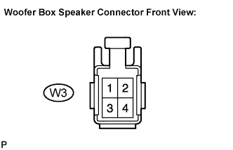
Measure the resistance between the woofer box speaker and the stereo component amplifier to check for an open circuit in the wire harness.
Measure the resistance between the each speaker and body ground to check for a short circuit in the wire harness.
|
| ||||
| OK | |
 |
| 2.INSPECT FRONT NO. 1 SPEAKER |
Resistance check.
Measure the resistance between the terminals of the speaker.
|
| ||||
| OK | |
|
| 3.INSPECT REAR SPEAKER |
Resistance check.
Measure the resistance between the terminals of the speaker.
|
| ||||
| OK | |
|
| 4.INSPECT FRONT NO. 2 SPEAKER |
Check that the malfunction disappears when another speaker in good condition is installed.
|
| ||||
| NG | |
|
| 5.CONFIRM MODEL |
| Result | Proceed to |
| 10 Speaker System | A |
| 6 Speaker System | B |
|
| ||||
| A | |
|
| 6.INSPECT WOOFER BOX SPEAKER |
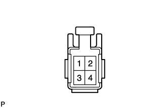 |
Resistance check.
Measure the resistance according to the value(s) in the table below.
| Tester connection | Condition | Specified condition |
| 1 - 3 | Always | Approximately 1.2 Ω |
| 2 - 4 | Always | Approximately 1.2 Ω |
|
| ||||
| OK | |
|
| 7.INSPECT REAR STEREO COMPONENT SPEAKER |
Check that the malfunction disappears when another speaker in good condition is installed.
|
| ||||
| NG | |
|
| 8.INSPECT FRONT STEREO COMPONENT SPEAKER |
Resistance check.
Measure the resistance between the terminals of the speaker.
|
| ||||
| OK | ||
 | ||
| ||
