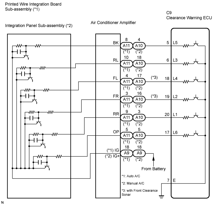
INTUITIVE PARKING ASSIST SYSTEM > Indicator Circuit |
| 1.CHECK HARNESS AND CONNECTOR (CLEARANCE WARNING ECU - AIR CONDITIONER AMPLIFIER) |
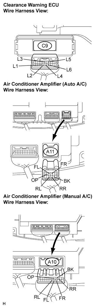 |
Disconnect the connectors from the clearance warning ECU C9 and air conditioner amplifier connector A10 or A11.
Measure the resistance according to the value(s) in the table below.
| Tester connection | Condition | Specified condition |
| BK - L5 | Always | Below 1 Ω |
| RL - L3 | Always | Below 1 Ω |
| FL - L4 | Always | Below 1 Ω |
| FR - L2 | Always | Below 1 Ω |
| RR - L1 | Always | Below 1 Ω |
| OP - L6 | Always | Below 1 Ω |
| BK - Body ground | Always | 10 kΩ or higher |
| RL - Body ground | Always | 10 kΩ or higher |
| FL - Body ground | Always | 10 kΩ or higher |
| FR - Body ground | Always | 10 kΩ or higher |
| RR - Body ground | Always | 10 kΩ or higher |
| OP - Body ground | Always | 10 kΩ or higher |
|
| ||||
| OK | |
 |
| 2.INSPECT INDICATOR |
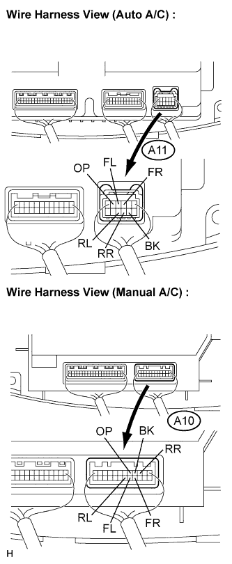 |
Remove the integration control & panel assembly with the connectors being connected.
Using a service wire, ground each terminal of the integration control & panel assembly connector.
Turn the ignition switch ON.
Check that each LED comes on.
| Indicators that come on | The terminals to which the service wire connects |
| Power indicator | OP |
| Back sonar | BK |
| Clearance sonar front RH | FR |
| Clearance sonar front LH | FL |
| Clearance sonar rear RH | RR |
| Clearance sonar rear LH | RL |
| Result | Proceed to |
| OK | A |
| NG | B (Auto A/C) |
| NG | C (Manual A/C) |
|
| ||||
|
| ||||
| A | ||
 | ||
| ||
| 3.INSPECT PRINTED WIRE INTEGRATION BOARD SUB-ASSEMBLY |
Check the malfunction disappears when a known good printed wire integration board sub-assembly is installed.
|
| ||||
| OK | ||
| ||
| ||
| 4.INSPECT INTEGRATION PANEL SUB-ASSEMBLY |
Check that the malfunction disappears when a known good integration panel sub-assembly is installed.
|
| ||||
| OK | ||
| ||
| ||

