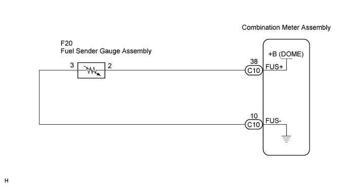
METER / GAUGE SYSTEM > Fuel Receiver Gauge Malfunction |
| 1.PERFORM ACTIVE TEST USING TECHSTREAM |
Connect Techstream to the DLC3.
Turn the ignition switch to the ON position.
Turn the tester ON.
Enter following menus: Body Electrical / Main Body / Active Test.
Check the operation by referring to the values in the table below.
| Tester Display | Test Part | Test Details | Diagnostic Note |
| Fuel Meter Operation | Fuel receiver gauge | EMPTY, 1/2, FULL | - |
|
| ||||
| OK | |
 |
| 2.READ VALUE USING TECHSTREAM |
Connect Techstream to the DLC3.
Turn the ignition switch to the ON position.
Turn the tester ON.
Enter following menus: Body Electrical / Combination Meter / Data List.
Check the values by referring to the values in the table below.
| Tester Display | Measurement Item/Range | Normal Condition | Diagnostic Note |
| Fuel Input | Fuel input signal Min.: 0, Max.: 255 | Fuel gauge indicates (F): 47 Fuel gauge indicates (1/2): 148 Fuel gauge indicates (E): 205 | - |
|
| ||||
| OK | |
|
| 3.INSPECT FUEL SENDER GAUGE ASSEMBLY |
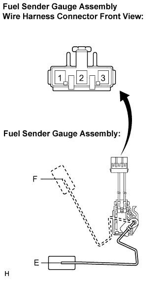 |
Disconnect the connector from the fuel sender gauge.
Check the the float moves smoothly between F and E.
Measure the resistance between terminals 1 and 2 of the connector according to the value(s) in the table below.
| Float Level | Resistance (Ω) |
| F | 13.5 to 16.5 |
| Between E and F | 13.5 to 414.5 (Gradually changes) |
| E | 405.5 to 414.5 |
|
| ||||
| OK | |
|
| 4.CHECK HARNESS AND CONNECTOR (COMBINATION METER ASSEMBLY - FUEL SENDER GAUGE ASSEMBLY) |
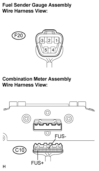 |
Disconnect the F20 and C10 connectors.
Measure the resistance according to the value(s) in the table below.
| Tester Connection | Condition | Specified Condition |
| F20-2 - C10-38 (FUS+) | Always | Below 1 Ω |
| F20-3 - C10-10 (FUS-) | Always | Below 1 Ω |
| F20-2 - Body ground | Always | 10 kΩ or higher |
| C10-10 (FUS-) - Body ground | Always | 10 kΩ or higher |
|
| ||||
| OK | ||
 | ||
| ||
