 |
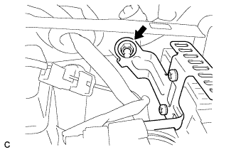
Remove the nut, and separate the fuel pump resistor.
CAMSHAFT TIMING OIL CONTROL VALVE ASSEMBLY > REMOVAL |
| 1. REMOVE WINDSHIELD WIPER MOTOR ASSEMBLY |
| 2. REMOVE FRONT OUTER COWL TOP PANEL SUB-ASSEMBLY |
|
Remove the nut, and separate the fuel pump resistor.
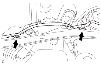 |
Remove the 2 clips, and separate the engine wire.
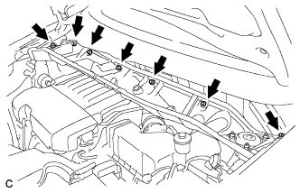 |
Remove the 7 bolts and front outer cowl top panel sub-assembly.
| 3. DRAIN ENGINE COOLANT |
Loosen the radiator drain cock plug.
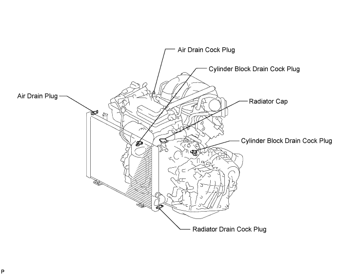
Remove the radiator cap sub-assembly from the radiator assembly.
Loosen the 2 cylinder block drain cock plugs.
| 4. REMOVE V-BANK COVER SUB-ASSEMBLY |
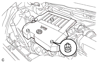 |
Hold the front of the V-bank cover and raise it to disengage the 2 clips on the front of the cover. Continue to raise the cover to disengage the clip on the rear of the cover and remove the cover.
| 5. REMOVE NO. 2 AIR CLEANER INLET |
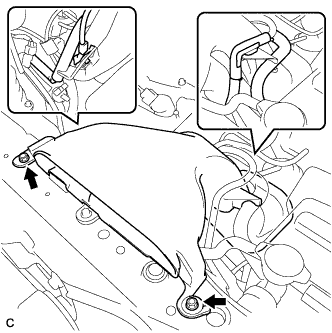 |
Disconnect the vacuum switching valve clamp.
Disconnect the 2 vacuum hoses.
Remove the 2 bolts and No. 2 air cleaner inlet.
| 6. REMOVE NO. 1 AIR CLEANER INLET |
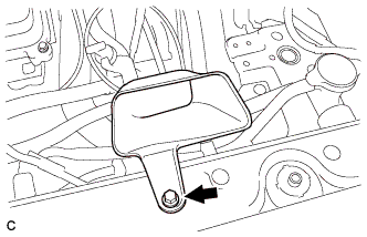 |
Remove the bolt and No. 1 air cleaner inlet.
| 7. REMOVE AIR CLEANER CAP SUB-ASSEMBLY |
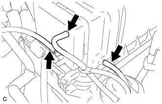 |
Disconnect the 3 vacuum hoses.
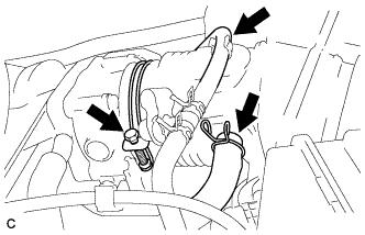 |
Remove the No. 2 ventilation hose and air cleaner hose band.
Disconnect the vacuum hose (EVAP) from the air cleaner hose.
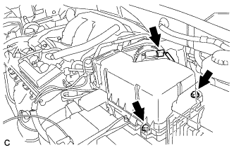 |
Disconnect the mass air flow meter connector.
Remove the 2 bolts and air cleaner cap sub-assembly.
| 8. REMOVE AIR CLEANER CASE SUB-ASSEMBLY |
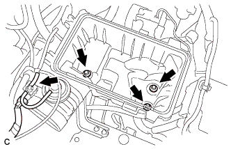 |
Disconnect the vacuum switching valve connector.
Disconnect the vacuum hose.
Remove the 3 bolts and air cleaner case.
| 9. REMOVE INTAKE AIR SURGE TANK ASSEMBLY |
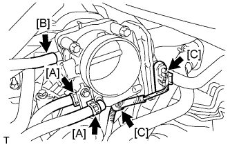 |
Disconnect the 2 water by-pass hoses from the throttle body [A].
Disconnect the vapor feed hose [B].
Disconnect the throttle body connector and clamp [C].
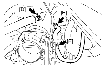 |
Disconnect the ventilation hose [D].
Disconnect the union to check valve hose [E].
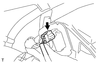 |
Disconnect the connector [F].
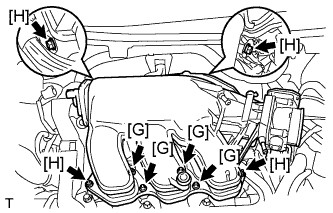 |
Using a 5 mm socket hexagon wrench, remove the 4 bolts [G].
Remove the 2 nuts, 2 bolts and intake air surge tank [H].
Remove the gasket from the intake air surge tank [I].
| 10. REMOVE CAMSHAFT TIMING OIL CONTROL VALVE ASSEMBLY (for Bank 1 Exhaust Side) |
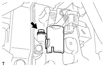 |
Disconnect the camshaft timing oil control valve assembly connector.
Remove the bolt and camshaft timing oil control valve assembly.
Remove the O-ring from the camshaft timing oil control valve.
| 11. REMOVE CAMSHAFT TIMING OIL CONTROL VALVE ASSEMBLY (for Bank 1 Intake Side) |
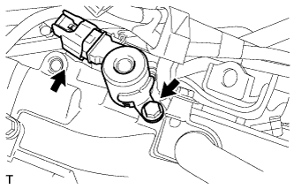 |
Disconnect the camshaft timing oil control valve assembly connector.
Remove the bolt and camshaft timing oil control valve assembly.
Remove the O-ring from the camshaft timing oil control valve.
| 12. REMOVE CAMSHAFT TIMING OIL CONTROL VALVE ASSEMBLY (for Bank 2 Exhaust Side) |
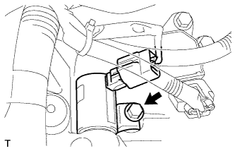 |
Disconnect the camshaft timing oil control valve assembly connector.
Remove the bolt and camshaft timing oil control valve assembly.
Remove the O-ring from the camshaft timing oil control valve.
| 13. REMOVE CAMSHAFT TIMING OIL CONTROL VALVE ASSEMBLY (for Bank 2 Intake Side) |
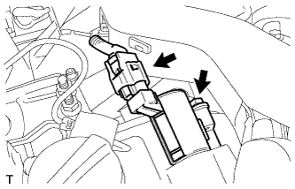 |
Disconnect the camshaft timing oil control valve assembly connector.
Remove the bolt and camshaft timing oil control valve assembly.
Remove the O-ring from the camshaft timing oil control valve.