 |
Disconnect the connector from the sender gauge.
METER / GAUGE SYSTEM > ON-VEHICLE INSPECTION |
| 1. INSPECT SPEEDOMETER |
Check the operation.
Using a speedometer tester, check the speedometer indication according to the table below.
| Chassis dynamometer indication | Acceptable range |
| 20 mph | 20.0 to 23.0 mph |
| 40 mph | 40.0 to 43.5 mph |
| 60 mph | 60.0 to 64.0 mph |
| 80 mph | 80.0 to 84.5 mph |
| 100 mph | 100.0 to 105.0 mph |
| Chassis dynamometer indication | Acceptable range Data in ( ) is for reference |
| 20 km/h | (17.5 to 21.5 km/h) |
| 40 km/h | 38.0 to 42.0 km/h |
| 60 km/h | 58.0 to 63.0 km/h |
| 80 km/h | 78.0 to 84.0 km/h |
| 100 km/h | 98.5 to 104.5 km/h |
| 120 km/h | 119.0 to 125.0 km/h |
| 140 km/h | 139.0 to 146.0 km/h |
| 160 km/h | 159.0 to 167.0 km/h |
Check the deviation from the acceptable value of the speedometer indication.
| 2. INSPECT TACHOMETER |
Check the operation.
Connect the tune-up test tachometer, and start the engine.
Compare the the test results with the tachometer indications.
| Chassis dynamometer indication (rpm) | Acceptable range (rpm) Data in ( ) are for reference |
| 700 | 630 to 770 |
| 1,000 | (900 to 1,100) |
| 2,000 | (1,850 to 2,150) |
| 3,000 | 2,800 to 3,200 |
| 4,000 | (3,800 to 4,200) |
| 5,000 | 4,800 to 5,200 |
| 6,000 | (5,750 to 6,250) |
| 7,000 | 6,700 to 7,300 |
| 8,000 | 7,700 to 8,300 |
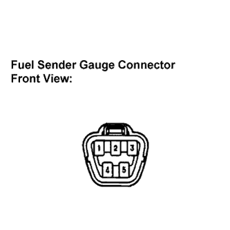
| 3. INSPECT FUEL RECEIVER GAUGE |
|
Disconnect the connector from the sender gauge.
Turn the ignition switch to the ON position, then check the position of the receiver gauge needle.
Connect the terminals 2 and 3 on the wire harness side connector of the fuel sender gauge.
Turn the ignition switch to the ON position, then check the position of the receiver gauge needle.
| 4. INSPECT FUEL LEVEL WARNING LIGHT |
Disconnect the connector from the sender gauge.
Turn the ignition switch to the ON position, then check the fuel level needle indicates EMPTY and the fuel level warning light comes on.
| 5. INSPECT OIL PRESSURE WARNING LIGHT |
Disconnect the connector from the low oil pressure switch.
Turn the ignition switch to the ON position.
Ground the terminal of the wire harness side connector, then check the low oil pressure warning light.
| 6. INSPECT OIL CHANGE REMINDER LIGHT RESETTING PROCEDURE |
| State | Condition | Specified State |
| Blinking | The vehicle runs 4,500 to 5,000 miles after the previous resetting. | The warning light for 15 seconds after turning the ignition switch to the ON position. |
| Continuously illuminated | The vehicle runs over 5,000 miles after the previous resetting. | The warning light for 15 seconds after turning the ignition switch to the ON position. |
Set the window to the odometer.
Turn the ignition switch off.
While pressing the reset switch, turn the ignition switch to the ON position. Keep pressing the reset switch for at least 5 seconds to complete the reset procedure. Check that the "000000" is displayed on the odometer.