| B |  |
| GO TO DTC CHART |
DTC P0771 Shift Solenoid "E" Performance (Shift Solenoid Valve SR) |
| DTC No. | DTC Detection Condition | Trouble Area |
| P0771 | The gear required by the ECM does not match the actual gear when driving (2-trip detection logic) |
|
| Related DTCs | P0771: Shift solenoid valve SR/Rationality check |
| Required sensors/Components | Shift solenoid valve SR, Speed sensor (NT), Speed sensor (NC), Crankshaft position sensor (NE) |
| Frequency of operation | Continuous |
| Duration | OFF malfunction (A) 1 sec. OFF malfunction (B) 3.5 sec. ON malfunction (A) Continuous ON malfunction (B) and (C) 0.8 sec. |
| MIL operation | 2 driving cycles |
| Sequence of operation | None |
| The monitor will run whenever this DTC is not present | P0115 - P0118 (ECT sensor) P0125 (Insufficient ECT for closed loop) P0500 (VSS) P0748, P0778, P0798 (Shift solenoid valve (range)) |
| ECT (Engine coolant temperature) | 10°C (50°F) or more |
| Transmission range | "D" |
| TFT (Transmission fluid temperature) | -20°C (-4°F) or more |
| TFT sensor circuit | Not circuit malfunction |
| ECT sensor circuit | Not circuit malfunction |
| Turbine speed sensor circuit | Not circuit malfunction |
| Intermediate shaft speed sensor circuit | Not circuit malfunction |
| Output speed sensor circuit | Not circuit malfunction |
| Shift solenoid valve SL1 circuit | Not circuit malfunction |
| Shift solenoid valve SL2 circuit | Not circuit malfunction |
| Shift solenoid valve SL3 circuit | Not circuit malfunction |
| Shift solenoid valve S4 circuit | Not circuit malfunction |
| Shift solenoid valve SR circuit | Not circuit malfunction |
| Shift solenoid valve DSL circuit | Not circuit malfunction |
| Electronic throttle system | Not circuit malfunction |
| ECM selected gear | 5th |
| Throttle valve opening angle | 5% or more |
| Vehicle speed | 10 km/h (6.2 mph) or more |
| ECM lock-up command | ON |
| ECM selected gear | 3rd, 4th or 5th |
| Vehicle speed | 25 km/h (15.5 mph) or more |
| ECM lock-up command | OFF |
| ECM selected gear | 1st |
| Vehicle speed | Less than 40 km/h (24.9 mph) |
| Throttle valve opening angle | 4.5% or more at engine speed 1,900 rpm (Varies with engine speed) |
| ECM selected gear | 3rd |
| Throttle valve opening angle | 4.5% or more at engine speed 1,900 rpm (Varies with engine speed) |
| Duration time from shift command of ECM | 15 sec. or more |
| ECM selected gear | 4th or 5th |
| Intermediate shaft speed/Output speed | 1.44 to 1.58 |
| Engine speed - Input (turbine) speed | 75 rpm or more |
| Difference between engine speed and input (turbine) speed | 150 rpm or more |
| Input (turbine) speed/Intermediate shaft speed | 0.93 to 1.07 |
| Input (turbine) speed/Intermediate shaft speed | 0.93 to 1.07 |
| Input (turbine) speed/Intermediate shaft speed | 0.64 to 0.74 |
| PERFORM ACTIVE TEST |
Warm up the engine.
Turn the ignition switch off.
Connect Techstream to the DLC3.
Turn the ignition switch to the ON position.
Turn on the tester.
Select the item "Powertrain / Engine and ECT / Active Test".
According to the display on the tester, perform the "Active Test".
| Tester Display | Test Part | Control Range | Diagnostic Note |
| Control the Shift Position | [Test Details] Operate the shift solenoid valve and set the each shift position by yourself. [Vehicle Condition]
| 1st/2nd/3rd/4th/5th | Possible to check the operation of the shift solenoid valves. |
| 1.CHECK OTHER DTCS OUTPUT (IN ADDITION TO DTC P0771) |
Connect Techstream to the DLC3.
Turn the ignition switch to the ON position and turn the Techstream main switch ON.
When you use Techstream:
Select the item "Powertrain / Engine and ECT / Trouble Codes".
Read the DTCs using Techstream.
| Result | Proceed to |
| P0771 | A |
| P0771 and other DTCs | B |
|
| ||||
| A | |
 |
| 2.INSPECT SHIFT SOLENOID VALVE SR |
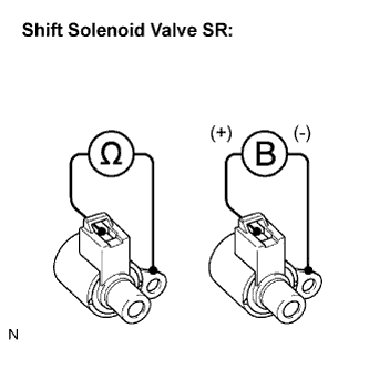 |
Remove the shift solenoid valve SR.
Measure the resistance according to the value(s) in the table below.
| Tester Connection | Specified Condition 20°C (68°F) |
| Solenoid Connector (SR) - Solenoid Body (SR) | 11 to 15 Ω |
Connect positive (+) lead to the terminal of solenoid connector, negative (-) lead to the solenoid body.
|
| ||||
| OK | |
|
| 3.INSPECT TRANSMISSION VALVE BODY ASSEMBLY |
|
| ||||
| OK | |
|
| 4.INSPECT TORQUE CONVERTER CLUTCH ASSEMBLY |
|
| ||||
| OK | ||
 | ||
| ||