DIFFERENTIAL CASE > INSPECTION |
| 1. INSPECT FRONT DIFFERENTIAL |
![]() |
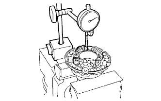
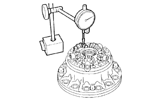
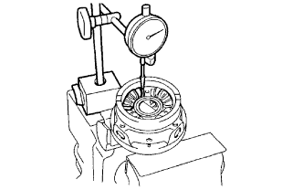
Using a dial indicator, measure the backlash of one pinion gear while holding the front differential side gear toward the case.
| Mark | Thickness | Mark | Thickness |
| A | 0.95 (0.0373) | F | 1.20 (0.0472) |
| B | 1.00 (0.0393) | G | 1.25 (0.0492) |
| C | 1.05 (0.0413) | H | 1.30 (0.0512) |
| D | 1.10 (0.0433) | J | 1.35 (0.0532) |
| E | 1.15 (0.0453) | K | 1.40 (0.0552) |
![]() |
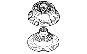
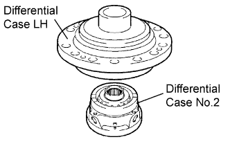
Engage the front differential side to the above mentioned front differential case.
Install the differential case LH to the front differential case and measure its center.
After that, remove the differential case LH.
![]() |
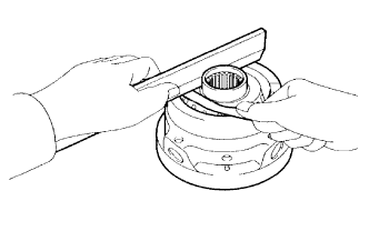
Using a straight edge and feeler gauge, measure the clearance between the front differential case and the front differential side gear.
| Mark | Thickness | Mark | Thickness |
| A | 0.95 (0.0373) | F | 1.20 (0.0472) |
| B | 1.00 (0.0393) | G | 1.25 (0.0492) |
| C | 1.05 (0.0413) | H | 1.30 (0.0512) |
| D | 1.10 (0.0433) | J | 1.35 (0.0532) |
| E | 1.15 (0.0453) | K | 1.40 (0.0552) |
| 2. INSPECT CENTER DIFFERENTIAL |
![]() |
Pressing and holding the differential spider toward the differential case RH, measure the pinion's backlash with a dial indicator as illustrated.
| Mark | Thickness | Mark | Thickness |
| MA | 0.80 (0.0313) | MH | 1.15 (0.0453) |
| MB | 0.85 (0.0333) | MJ | 1.20 (0.0472) |
| MC | 0.90 (0.0353) | MK | 1.25 (0.0492) |
| MD | 0.95 (0.0373) | ML | 1.30 (0.0512) |
| ME | 1.00 (0.0393) | MM | 1.35 (0.0532) |
| MF | 1.05 (0.0413) | MN | 1.40 (0.0552) |
| MG | 1.10 (0.0433) | - | - |
![]() |
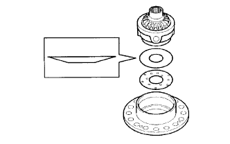
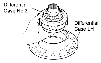
Temporarily install the differential side gear thrust washer No.2 LH, center differential side gear conical spring washer and differential case No.2 to the differential case LH.
![]() |
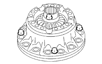
Install the differential intermediate case to the above and fix them with 4 bolts.
![]() |
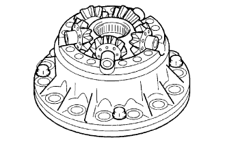
remove the differential spider, 5 center differential pinions and 5 center differential pinion thrust washers from the differential case RH. Put them in the differential intermediate case and fix the case.
![]() |
Pressing and holding the differential spider toward the differential intermediate case, measure the pinion's backlash with a dial indicator.
| Mark | Thickness | Mark | Thickness |
| MA | 0.80 (0.0313) | MH | 1.15 (0.0453) |
| MB | 0.85 (0.0333) | MJ | 1.20 (0.0472) |
| MC | 0.90 (0.0353) | MK | 1.25 (0.0492) |
| MD | 0.95 (0.0373) | ML | 1.30 (0.0512) |
| ME | 1.00 (0.0393) | MM | 1.35 (0.0532) |
| MF | 1.05 (0.0413) | MN | 1.40 (0.0552) |
| MG | 1.10 (0.0433) | - | - |
![]() |
Remove the 4 bolts and disconnect the differential case LH from the differential intermediate case.
![]() |
Remove the differential case No.2 from the differential case LH.
| 3. ADJUST TAPERED ROLLER BEARING PRELOAD |
![]() |
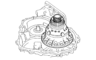
Install the intermediate case to the differential case LH and fix them with 4 bolts.
Install the differential assembly to the transaxle case.
![]() |
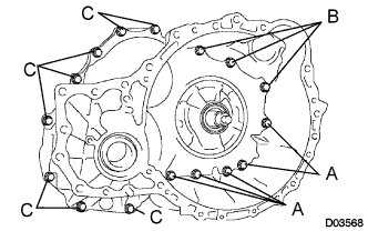
Clean the matching surfaces of the transaxle case and transaxle housing.
Install the transaxle housing to the transaxle case and tighten them with the 16 bolts.
![]() |
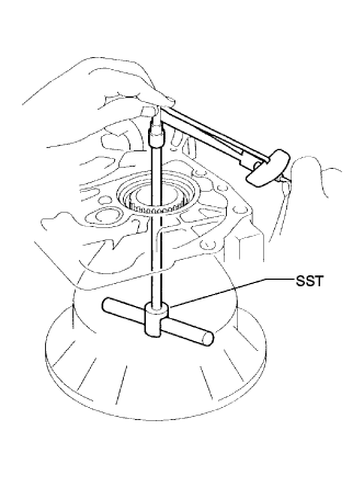
Using SST, turn the differential assembly right and left 2 or 3 times to allow the bearing settle.
Using SST and a torque wrench, measure the turning torque of the differential case assembly.
| Mark | Thickness | Mark | Thickness |
| 0 | 2.00 (0.0787) | 9 | 2.45 (0.0965) |
| 1 | 2.05 (0.0807) | A | 2.50 (0.0984) |
| 2 | 2.10 (0.0827) | B | 2.55 (0.1004) |
| 3 | 2.15 (0.0846) | C | 2.60 (0.1024) |
| 4 | 2.20 (0.0866) | D | 2.65 (0.1043) |
| 5 | 2.25 (0.0886) | E | 2.70 (0.1063) |
| 6 | 2.30 (0.0906) | F | 2.75 (0.1083) |
| 7 | 2.35 (0.0925) | G | 2.80 (0.1102) |
| 8 | 2.40 (0.0945) | H | 2.00 (0.1122) |
![]() |
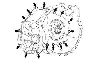
Remove the 16 bolts and the transaxle housing.
![]() |
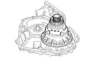
Remove the differential assembly.