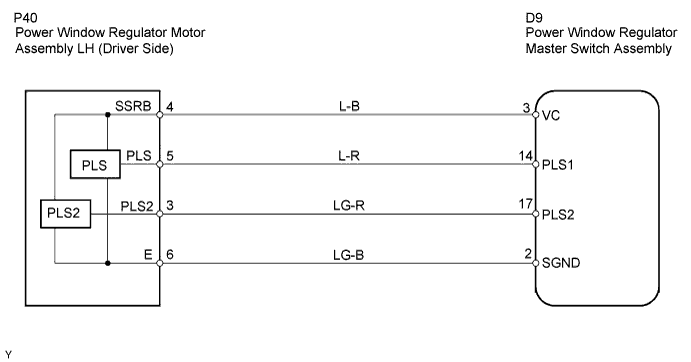
POWER WINDOW CONTROL SYSTEM (w/ Jam Protection Function) > Auto Up / Down Function does not Operate |
| 1.CHECK MANUAL UP/DOWN FUNCTION (DRIVER SIDE) |
Check that the door glass can be operated manually.
|
| ||||
| OK | |
 |
| 2.CHECK ILLUMINATION OF POWER WINDOW MASTER SWITCH |
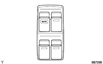 |
Turn the ignition switch ON.
Operate the AUTO (drive side) switch of the master switch.
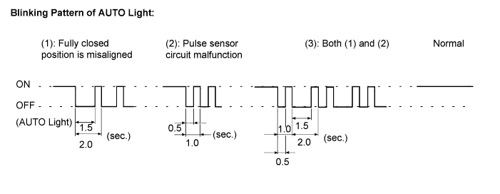
Check the blinking pattern of the AUTO light as shown in the illustration.
If pattern (1) is displayed, proceed to A.
If pattern (2) or (3) is displayed, proceed to B.
If the normal pattern is displayed, proceed to C.
|
| ||||
|
| ||||
| A | |
|
| 3.RESET POWER WINDOW REGULATOR MOTOR |
|
| ||||
| NG | |
|
| 4.CHECK WIRE HARNESS (MASTER SWITCH - MOTOR) (MASTER SWITCH - BODY GROUND) |
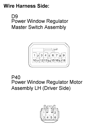 |
Disconnect the D9 master switch connector.
Disconnect the P40 motor connector (driver side).
Check the resistance between the wire harness side connectors.
| Terminal No. | Specified Condition |
| D9-3 (VC) - P40-4 (SSRB) | Below 1 Ω |
| D9-14 (PLS1) - P40-5 (PLS) | |
| D9-17 (PLS2) - P40-3 (PLS2) | |
| D9-2 (SGND) - P40-6 (E) |
Check the resistance between the D9 master switch connector and body ground.
| Terminal No. | Specified Condition |
| D9-3 (VC) - Body ground | 10 kΩ or higher |
| D9-14 (PLS1) - Body ground | |
| D9-17 (PLS2) - Body ground | |
| D9-2 (SGND) - Body ground |
|
| ||||
| OK | ||
 | ||
| ||

