Home › ENGINE › 2GR-FE CHARGING › GENERATOR

GENERATOR > REMOVAL

for Preparation Click here


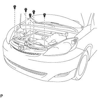
1. REMOVE V-BANK COVER SUB-ASSEMBLY


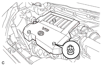
    A162365
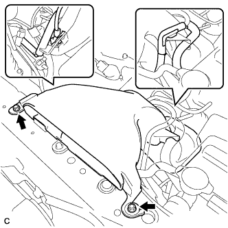
  1. Hold the front of the V-bank cover and raise it to disengage the 2 clips on the front of the cover. Continue to raise the cover to disengage the clip on the rear of the cover and remove the cover.

    NOTICE:
    Attempting to disengage both front and rear clips at the same time may cause the cover to break.

2. REMOVE FRONT WHEEL RH


3. REMOVE NO. 1 ENGINE UNDER COVER


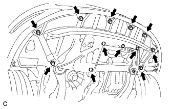
    A162362
  1. Remove the 8 bolts, 4 clips and No. 1 engine under cover assembly.


4. REMOVE FRONT FENDER APRON SEAL RH


    A162371
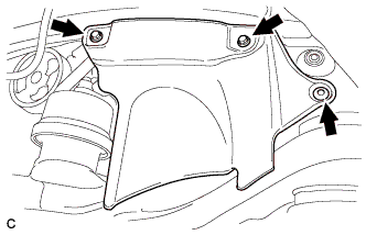
  1. Remove the 2 bolts, clip and front fender apron seal RH.


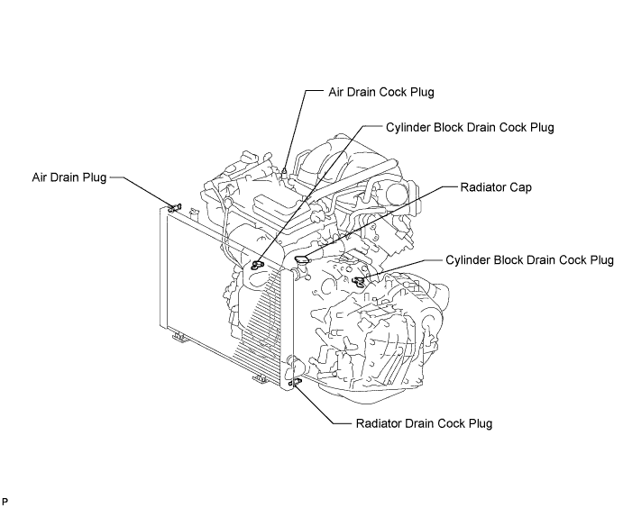
5. DRAIN ENGINE COOLANT


  1. Loosen the radiator drain cock plug.


    A161473E01

    HINT:
    Collect the coolant in a container and dispose of it according to the regulations in your area.

  1. Remove the radiator cap sub-assembly from the radiator assembly.

    NOTICE:
    Do not remove the radiator cap sub-assembly while the engine and radiator are still hot. Pressurized, hot engine coolant and steam may be released and cause serious burns.

  1. Loosen the 2 cylinder block drain cock plugs.


6. REMOVE NO. 2 AIR CLEANER INLET


    A133004
  1. Disconnect the vacuum switching valve clamp.

  1. Disconnect the 2 vacuum hoses.

  1. Remove the 2 bolts and No. 2 air cleaner inlet.


7. REMOVE BATTERY


    A155033
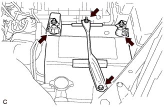
  1. Disconnect the negative battery terminal.

  1. Disconnect the positive battery terminal.

  1. Loosen the nut, and remove the bolt and battery clamp.

  1. Remove the battery and battery tray.


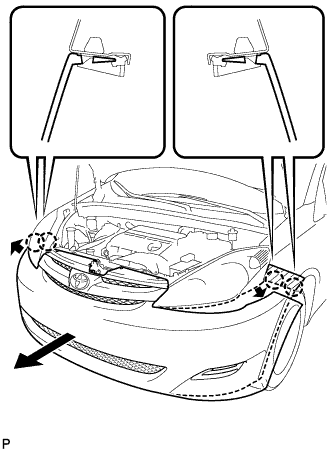
8. REMOVE FRONT BUMPER ASSEMBLY


    B125278
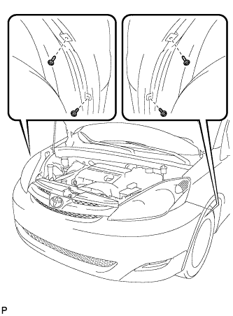
  1. Remove the 4 screws and separate the fender liner from the front bumper assembly.


    B125279
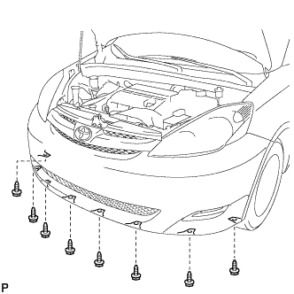
  1. Remove the 8 screws and separate the engine under cover from the front bumper assembly.


    B125280
  1. Remove the 5 clips.


    B125281
  1. Disengage the claws on the left and right sides of the front bumper and pull the front bumper toward the front of the vehicle as shown in the illustration.

    HINT:
    1. Apply protective tape to the bottom part of the front fender to prevent it from being damaged.
    2. Disconnect the connectors if necessary.


9. REMOVE FRONT BUMPER ENERGY ABSORBER


10. REMOVE NO. 1 AIR CLEANER INLET


    A155040
  1. Remove the bolt and No. 1 air cleaner inlet.


11. DISCONNECT RADIATOR RESERVE TANK HOSE OR PIPE


    A161455
  1. Disconnect the radiator reserve tank hose or pipe from the radiator.


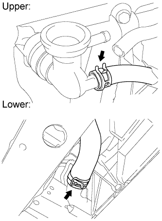
12. DISCONNECT NO. 1 RADIATOR HOSE


    A162804E01
  1. Disconnect both connections of the No. 1 radiator hose from the radiator.


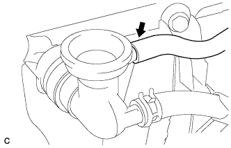
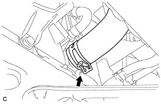
13. DISCONNECT NO. 2 RADIATOR HOSE


    A161461
  1. Disconnect the No. 2 radiator hose from the radiator.


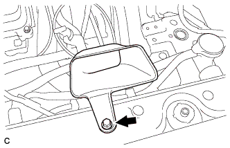
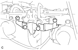
14. REMOVE HOOD LOCK RELEASE LEVER PROTECTOR


    A161456
  1. Disengage the 4 claws and remove the hood lock release lever protector.


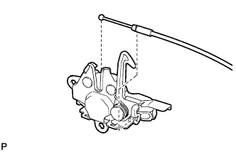
15. REMOVE HOOD LOCK ASSEMBLY
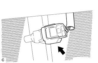
  1. With Hood Courtesy Switch:

    1. Disconnect the connector.


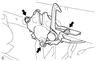
    A161457
  1. Remove the 3 bolts.


    A162807
  1. Disconnect the cable and remove the hood lock assembly.


16. REMOVE HOOD LOCK SUPPORT SUB-ASSEMBLY


    A161459
  1. Disconnect the ambient temperature sensor connector.


    A161458E01
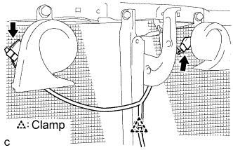
  1. Detach the clamp.

  1. Disconnect the low pitched horn and high pitched horn connectors.


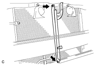
    A161460
  1. Remove the 2 bolts and hood lock support sub-assembly.


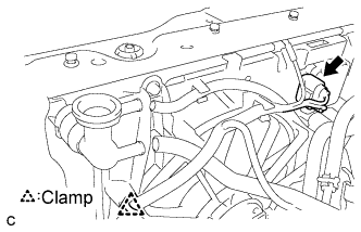
17. DISCONNECT COOLING FAN ECU CONNECTOR


    A161472E01
  1. Disconnect the cooling fan ECU connector.

  1. Detach the clamp.


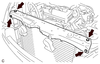
18. REMOVE RADIATOR UPPER SUPPORT SUB-ASSEMBLY


    A161463
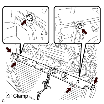
  1. Remove the 4 bolts and radiator upper support sub-assembly.


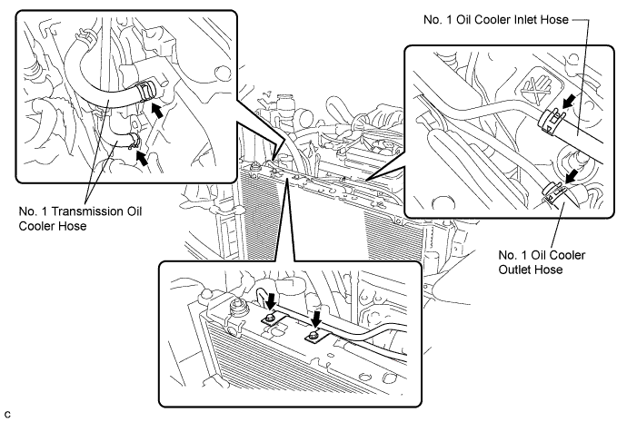
19. DISCONNECT NO. 2 OIL COOLER OUTLET TUBE SUB-ASSEMBLY


  1. Disconnect the No. 1 oil cooler inlet and No. 1 oil cooler outlet hoses from the No. 2 oil cooler outlet tube sub-assembly.


    A161467E02

  1. Disconnect the No. 1 transmission oil cooler hoses from the radiator.

  1. Remove the 2 bolts and No. 2 oil cooler outlet tube sub-assembly.


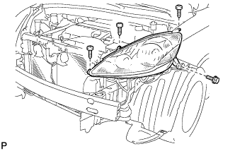
20. REMOVE HEADLIGHT ASSEMBLY RH
  1. Disconnect the connectors.


    E119908
  1. Remove the bolt, 3 screws and headlight assembly.


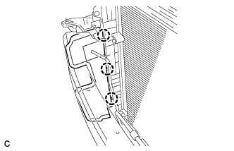
21. REMOVE RADIATOR SIDE DEFLECTOR RH


    A161464
  1. Disengage the 3 claws and remove the radiator side deflector RH.


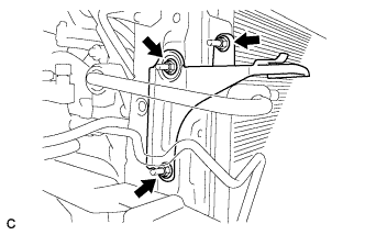
22. REMOVE HEADLIGHT BRACKET RH


    A161465
  1. Remove the 3 nuts and headlight bracket RH.


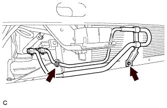
23. REMOVE PRESSURE FEED TUBE ASSEMBLY


    A161466
  1. Remove the 2 bolts.


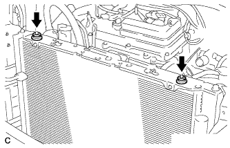
24. REMOVE RADIATOR SUPPORT CUSHION


    A162805
  1. Remove the 2 radiator support cushions from the No. 1 radiator support.


25. REMOVE NO. 1 RADIATOR SUPPORT
  1. Detach the clamp.


    A161469E01
  1. Remove the 6 bolts and No. 1 radiator support.


26. REMOVE RADIATOR ASSEMBLY WITH FAN SHROUD AND FAN MOTOR


    A161470
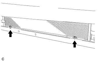
  1. Remove the 2 bolts and separate the condenser assembly from the radiator assembly with fan shroud and fan motor.


    A161471
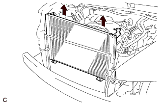
  1. Remove the radiator assembly with fan shroud and fan motor from the body.


27. REMOVE V-RIBBED BELT


    A162386E01
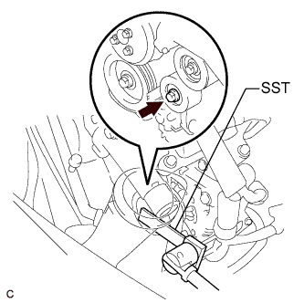
  1. Using SST, release the belt tension by turning the belt tensioner counterclockwise, and remove the V-ribbed belt from the belt tensioner.

    SST
    09249-63010  


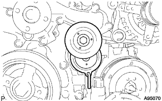
    A095070
  1. While turning the belt tensioner counterclockwise, align with its holes, and then insert the 5 mm bi-hexagon wrench into the holes to fix the V-ribbed belt tensioner.


28. REMOVE GENERATOR ASSEMBLY


    A162681
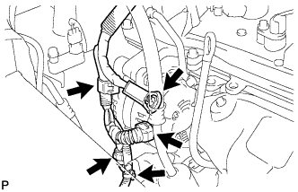
  1. Remove the terminal cap.

  1. Remove the nut and disconnect the wire harness from terminal B.

  1. Disconnect the generator connector from the generator assembly.

  1. Disconnect the connector from the compressor and magnetic clutch.

  1. Disconnect the 2 wire harness clamps.


    A162682
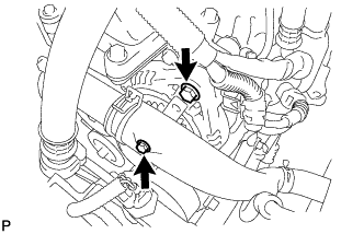
  1. Remove the 2 bolts.


    A162683E01
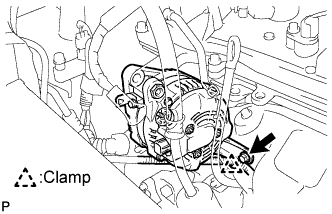
  1. Remove the bolt from the cylinder block.

  1. Disconnect the wire harness clamp and remove the generator assembly.


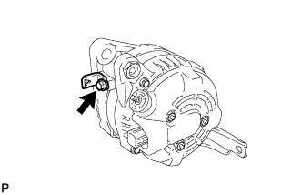
    A162684
  1. Remove the bolt and wire harness clamp stay.


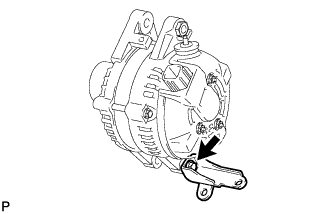
    A162685
  1. Remove the bolt and bracket.