Home › BRAKE › BRAKE CONTROL › VEHICLE STABILITY CONTROL SYSTEM

DTC    C1246/46    Master Cylinder Pressure Sensor Malfunction

for Preparation Click here


DESCRIPTION

Master cylinder pressure sensor is connected to the skid control ECU in the actuator.

DTC Code
DTC Detection Condition
Trouble Area
C1246/46
When any of the following is detected:
  1. When the vehicle speed is 7 km/h (4 mph) or more and PMC terminal voltage of skid control ECU exceeds 0.86 V, the condition that the voltage does not change by 0.005 V or more continues for 30 sec.
  2. Noise in terminal PMC of skid control ECU occurs 7 times or more within 5 sec.
  3. When the stop light switch is off, the condition that PMC terminal voltage of skid control ECU is 0.86 V or more, or less than 0.3 V continues for 5 sec. or more.
  4. When IG1 terminal voltage is between 9.5 and 18.5 V, the condition that the VCM terminal voltage of skid control ECU is out of the range from 4.4 to 5.6 V continues for 1.2 sec. or more.
  5. When VCM terminal voltage of skid control ECU is between 4.4 and 5.6 V, the condition that the PMC terminal voltage of skid control ECU is out of the range from 0.19 to 4.57 V continues for 1.2 sec. or more.
  1. Master cylinder pressure sensor
  2. Master cylinder pressure sensor circuit

INSPECTION PROCEDURE

1.READ VALUE ON TECHSTREAM (MASTER CYLINDER PRESSURE SENSOR)
  1. Connect Techstream to the DLC3.

  1. Start the engine.

  1. Select the Data List mode on Techstream.

    ABS / VSC / TRAC: 
    Tester Display
    Measurement Item/Range
    Normal Condition
    Master Cylinder Sensor
    Master cylinder pressure sensor 1 reading / min.: 0 V, max.: 5 V
    When brake pedal is released : 0.3 to 0.9 V

  1. Check that the brake fluid pressure value of the master cylinder pressure sensor indicated on Techstream, changes when the brake pedal is depressed.

    OK:
    Brake fluid pressure value should change.

    NOTICE:
    When replacing the brake actuator assembly, perform zero point calibration (Click here).


NG
Go to step 2
OK

REPLACE BRAKE ACTUATOR ASSEMBLY 

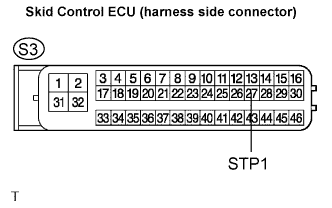
2.INSPECT SKID CONTROL ECU (STP1 TERMINAL)
  1. Disconnect the skid control ECU connector.


    G024767E58
  1. Measure the voltage according to the value(s) in the table below.

    Standard voltage:
    Tester Connection
    Condition
    Specified Condition
    S3-27 (STP1) - Body ground
    Brake pedal depressed
    8 to 14 V
    S3-27 (STP1) - Body ground
    Brake pedal depressed
    Below 1 V

    NOTICE:
    When replacing the brake actuator assembly, perform zero point calibration (Click here).


NG
REPAIR OR REPLACE STOP LIGHT SWITCH CIRCUIT
OK

REPLACE BRAKE ACTUATOR ASSEMBLY