Home › BRAKE › BRAKE CONTROL › VEHICLE STABILITY CONTROL SYSTEM

DTC    C1232/32    Stuck in Deceleration Sensor

DTC    C1234/34    Yaw Rate Sensor Malfunction

DTC    C1243/43    Acceleration Sensor Stuck Malfunction

DTC    C1244/44    Open or Short in Deceleration Sensor Circuit

DTC    C1245/45    Acceleration Sensor Output Malfunction

DTC    C1381/97    Acceleration Sensor Power Supply Voltage Malfunction

for Preparation Click here


DESCRIPTION

The yaw rate sensor and deceleration sensor signal is sent to the skid control ECU through the CAN communication system. When there is a malfunction in the communication, it will be detected by the diagnosis function.

DTC Code
DTC Detection Condition
Trouble Area
C1232/32
At a vehicle speed of 10 km/h (6 mph) or more, either GL1 or GL2 (input signal) does not change for 30 sec. or more.
Yaw rate and deceleration sensor
C1234/34
The yaw rate sensor malfunction signal is received
Yaw rate and deceleration sensor
C1243/43
While vehicle speed becomes 0 km/h (0 mph) from 30 km/h (18 mph) or more, the condition that both GL1 and GL2 signals of ECU terminals do not change 2 LSB or more continued in a sequence 16 times.
  1. Yaw rate and deceleration sensor
  2. Yaw rate and deceleration sensor circuit
C1244/44
When either of the following is detected:
  1. With vehicle speed at 0 km/h, after the difference of output absolute value of G conversion value between deceleration sensor terminals GL1 and GL2 becomes 0.6 G or more, and the condition that does not become 0.4 G continues for 60 sec. or more.
  2. Deceleration sensor malfunction signal is received.
  1. Yaw rate and deceleration sensor
  2. Yaw rate and deceleration sensor circuit
C1245/45
At the vehicle speed of 30 km/h (18 mph) or more, the acceleration and deceleration values calculated from the deceleration sensor values and from vehicle speed are different, and the condition that the difference exceeds 0.35 G continues for 60 sec. or more.
  1. Yaw rate and deceleration sensor
  2. Yaw rate and deceleration sensor circuit
C1381/97
With vehicle speed at 3 km/h or more, malfunction signal of deceleration sensor terminal IG1 is received for 10 sec. or more.
  1. Yaw rate and deceleration sensor
  2. Yaw rate and deceleration sensor power source circuit

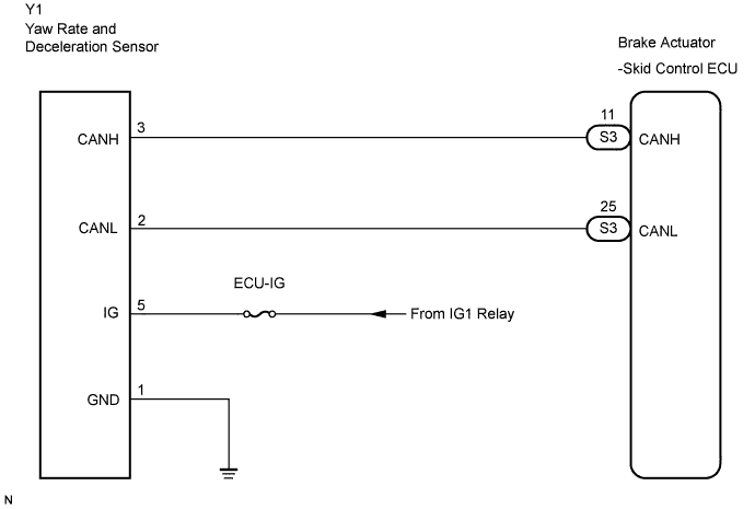
WIRING DIAGRAM


C132917E08


INSPECTION PROCEDURE

HINT:
When U0073/94, U0100/65, U0123/62, U0124/95 or U0126/63 are output accompanied with C1232/32, C1234/34, C1243/43, C1244/44, C1245/45 or C1381/97, inspect and repair the trouble areas indicated by U0073/94, U0100/65, U0123/62, U0124/95 or U0126/63 first.

1.CHECK YAW RATE AND DECELERATION SENSOR INSTALLATION
  1. Check that the yaw rate and deceleration sensor has been installed properly (Click here).

    OK:
    The sensor should be tightened to the specified torque.
    The sensor should not be tilted.


NG
INSTALL YAW RATE AND DECELERATION SENSOR CORRECTLY
OK


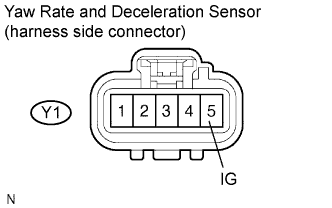
2.INSPECT YAW RATE AND DECELERATION SENSOR (IG TERMINAL)
  1. Disconnect the yaw rate and deceleration sensor connector.

  1. Turn the ignition switch to the ON position.


    F045082E08
  1. Measure the voltage according to the value(s) in the table below.

    Standard voltage:
    Tester Connection
    Specified Condition
    Y1-5 (IG) - Body ground
    10 to 14 V


NG
REPAIR OR REPLACE HARNESS OR CONNECTOR (IG CIRCUIT)
OK


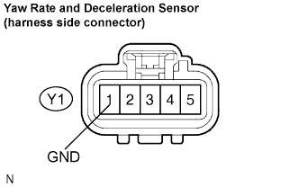
3.INSPECT YAW RATE AND DECELERATION SENSOR (GND TERMINAL)
  1. Disconnect the yaw rate and deceleration sensor connector.


    F045082E09
  1. Measure the resistance according to the value(s) in the table below.

    Standard resistance:
    Tester Connection
    Specified Condition
    Y1-1 (GND) - Body ground
    Below 1 Ω


NG
REPAIR OR REPLACE HARNESS OR CONNECTOR (GND CIRCUIT)
OK

REPLACE YAW RATE AND DECELERATION SENSOR