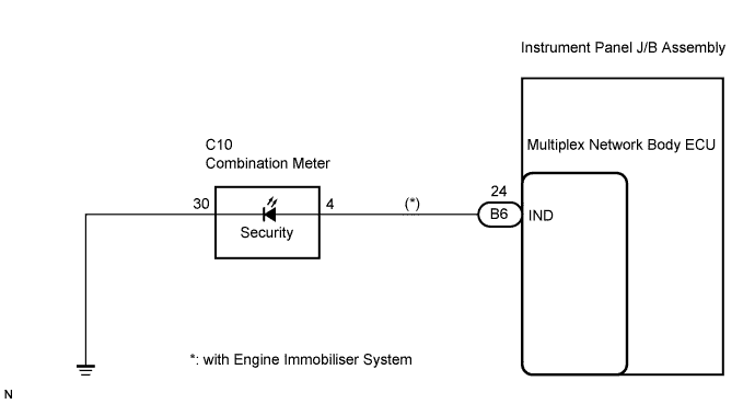
THEFT DETERRENT SYSTEM > Security Indicator Light Circuit |
| 1.INSPECT COMBINATION METER ASSEMBLY |
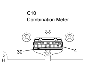 |
Remove the combination meter assembly.
Apply battery voltage between the terminals of the indicator, and check the lighting condition of the security indicator.
| Measurement Condition | Specified Condition |
| Battery positive (+) → Terminal C10-4 Battery negative (-) → Terminal C10-30 | Lights up |
|
| ||||
| OK | |
 |
| 2.CHECK HARNESS AND CONNECTOR (COMBINATION METER ASSEMBLY - MULTIPLEX NETWORK BODY ECU) |
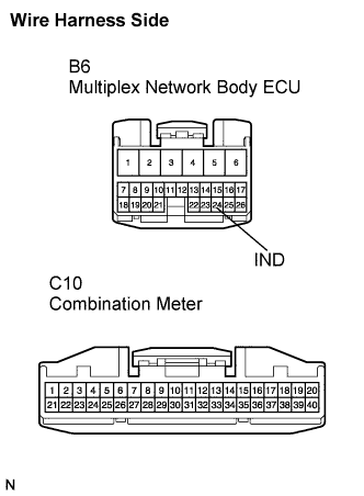 |
Disconnect the B6 ECU connector.
Disconnect the C10 meter connector.
Measure the resistance according to the value(s) in the table below.
| Symbol (Tester Connection) | Specified Condition |
| IND (B6-24) - C10-4 | Below 1 Ω |
| IND (B6-24) - Body ground | 10 kΩ or higher |
|
| ||||
| OK | |
|
| 3.CHECK HARNESS AND CONNECTOR (COMBINATION METER - BODY GROUND) |
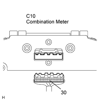 |
Measure the resistance according to the value(s) in the table below.
| Tester Connection | Specified Condition |
| C10-30 - Body ground | Below 1 Ω |
|
| ||||
| OK | ||
 | ||
| ||
