MULTIPLEX COMMUNICATION SYSTEM > TERMINALS OF ECU |
| MULTIPLEX NETWORK GATEWAY ECU |
Disconnect the G4 ECU connector.

Measure the voltage between the specified terminals on the wire harness side connector.
| Terminal No. (Symbols) | Wiring Color | Terminal Description | Condition | Specified Condition |
| G4-1 (IG) - Body ground | B-R - Body ground | Power supply (IG) | Ignition switch: ON | 11 to 14 V |
| G4-2 (ACC) - Body ground | P - Body ground | Power source (ACC) | Ignition switch: ACC | 11 to 14 V |
| G4-10 (BATT) - Body ground | W-L - Body ground | Power supply (Battery) | Always | 11 to 14 V |
Measure the resistance between the specified terminals on the wire harness side connector.
| Terminal No. (Symbols) | Wiring Color | Terminal Description | Condition | Specified Condition |
| G4-3 (MPD1) - Body ground | R-G - Body ground | MPX line | Always | 10 kΩ or higher |
| G4-12 (MPD2) - Body ground | R-L - Body ground | MPX line | Always | 10 kΩ or higher |
| G4-24 (GND) - Body ground | W-B - Body ground | Ground | Always | Below 1 Ω |
| MULTIPLEX NETWORK BODY ECU |
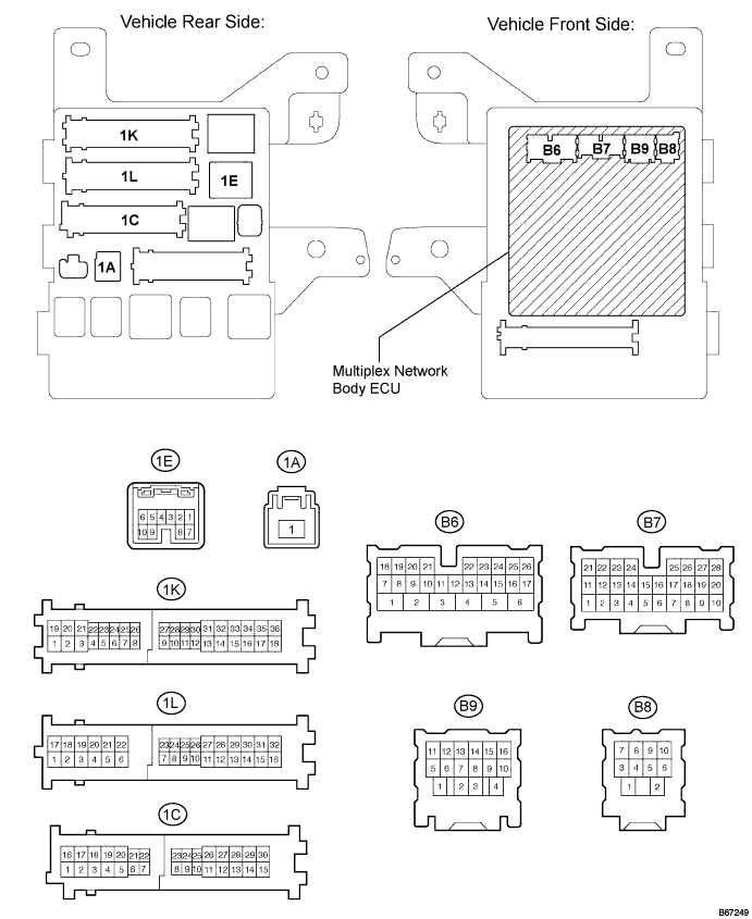
Disconnect the B7 ECU, 1A, 1C, 1E, 1K and 1L junction block connectors.

Measure the voltage between the specified terminals on the wire harness side connector.
| Terminal No. (Symbols) | Wiring Color | Terminal Description | Condition | Specified Condition |
| 1A-1 - Body ground | W - Body ground | Power supply (Battery) | Always | 11 to 14 V |
| 1C-30 (ALTB) - Body ground | B - Body ground | Power supply (Battery) | Always | 11 to 14 V |
Measure the resistance between the specified terminals on the wire harness side connector.
| Terminal No. (Symbols) | Wiring Color | Terminal Description | Condition | Specified Condition |
| 1E-7 (MPX1) - Body ground | R-L - Body ground | MPX line | Always | 10 kΩ or higher |
| B7-21 (MPX2) - Body ground | R-L - Body ground | MPX line | Always | 10 kΩ or higher |
| 1L-16 (GND1) - Body ground | W-B - Body ground | Ground | Always | Below 1 Ω |
| 1K-17 (GND2) - Body ground | W-B - Body ground | Ground | Always | Below 1 Ω |

| AIRBAG SENSOR ASSEMBLY |
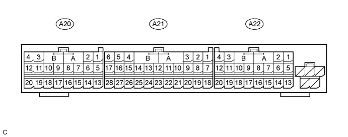
Disconnect the A21 ECU connector.

Measure the voltage between the specified terminals on the wire harness side connector.
| Terminal No. (Symbols) | Wiring Color | Terminal Description | Condition | Specified Condition |
| A21-5 (IG2) - Body ground | B-O - Body ground | Power supply (IG) | Ignition switch: ON | 11 to 14 V |
Measure the resistance between the specified terminals on the wire harness side connector.
| Terminal No. (Symbols) | Wiring Color | Terminal Description | Condition | Specified Condition |
| A21-24 (MPX1) - Body ground | R-L - Body ground | MPX line | Always | 10 kΩ or higher |
| A21-22 (MPX2) - Body ground | R-L - Body ground | MPX line | Always | 10 kΩ or higher |
| A21-27 (E1) - Body ground | W-B - Body ground | Ground | Always | Below 1 Ω |

| A21-28 (E2) - Body ground | W-B - Body ground | Ground | Always | Below 1 Ω |

| SEAT POSITION CONTROL ECU (with Driving Position Memory) |
Disconnect the P58 and P59 ECU connectors.

Measure the voltage between the specified terminals on the wire harness side connector.
| Terminal No. (Symbols) | Wiring Color | Terminal Description | Condition | Specified Condition |
| P59-4 (IG) - Body ground | Y - Body ground | Power supply (IG) | Ignition switch: ON | 11 to 14 V |
| P59-8 (SYSB) - Body ground | W-L - Body ground | Power supply (Battery) | Always | 11 to 14 V |
| P58-5 (+B) - Body ground | V - Body ground | Power supply (Battery) | Always | 11 to 14 V |
Measure the resistance between the specified terminals on the wire harness side connector.
| Terminal No. (Symbols) | Wiring Color | Terminal Description | Condition | Specified Condition |
| P59-1 (MPX1) - Body ground | R-L - Body ground | MPX line | Always | 10 kΩ or higher |
| P58-1 (GND) - Body ground | W-B - Body ground | Ground | Always | Below 1 Ω |
| AIR CONDITIONING AMPLIFIER |
Disconnect the A9 ECU connector.

Measure the voltage between the specified terminals on the wire harness side connector.
| Terminal No. (Symbols) | Wiring Color | Terminal Description | Condition | Specified Condition |
| A9-20 (B) - Body ground (*1) | W-L - Body ground | Power supply (Battery) | Always | 11 to 14 V |
| A9-17 (+B) - Body ground (*2) | W-L - Body ground | Power supply (Battery) | Always | 11 to 14 V |
| A9-19 (ACC) - Body ground (*1) | P - Body ground | Power supply (ACC) | Ignition switch: ACC | 11 to 14 V |
| A9-40 (ACC) - Body ground (*2) | P - Body ground | Power supply (ACC) | Ignition switch: ACC | 11 to 14 V |
| A9-18 (IG) - Body ground (*1) | R-Y - Body ground | Power supply (IG) | Ignition switch: ON | 11 to 14 V |
| A9-18 (IG+) - Body ground (*2) | R-Y - Body ground | Power supply (IG) | Ignition switch: ON | 11 to 14 V |
Measure the resistance between the specified terminals on the wire harness side connector.
| Terminal No. (Symbols) | Wiring Color | Terminal Description | Condition | Specified Condition |
| A9-2 (MPX+) - Body ground (*1) | V - Body ground | MPX line | Always | 10 kΩ or higher |
| A9-4 (MPX+) - Body ground (*2) | V - Body ground | MPX line | Always | 10 kΩ or higher |
| A9-3 (MPX-) - Body ground (*1) | R-L - Body ground | MPX line | Always | 10 kΩ or higher |
| A9-5 (MPX-) - Body ground (*2) | R-L - Body ground | MPX line | Always | 10 kΩ or higher |
| A9-1 (GND) - Body ground (*1) | W-B - Body ground | Ground | Always | Below 1 Ω |
| A9-6 (GND) - Body ground (*2) | W-B - Body ground | Ground | Always | Below 1 Ω |
| COMBINATION METER |
Disconnect the C10 ECU connector.

Measure the voltage between the specified terminals on the wire harness side connector.
| Terminal No. (Symbols) | Wiring Color | Terminal Description | Condition | Specified Condition |
| C10-12 (+B) - Body ground | W-L - Body ground | Power supply (Battery) | Always | 11 to 14 V |
| C10-32 (IG+) - Body ground | B-R - Body ground | Power supply (IG) | Ignition switch: ON | 11 to 14 V |
Measure the resistance between the specified terminals on the wire harness side connector.
| Terminal No. (Symbols) | Wiring Color | Terminal Description | Condition | Specified Condition |
| C10-29 (MPX1) - Body ground | R-L - Body ground | MPX line | Always | 10 kΩ or higher |
| C10-28 (MPX2) - Body ground | V - Body ground | MPX line | Always | 10 kΩ or higher |
| C10-30 (ES) - Body ground | BR - Body ground | Ground | Always | Below 1 Ω |
| POWER SLIDE DOOR ECU RH |
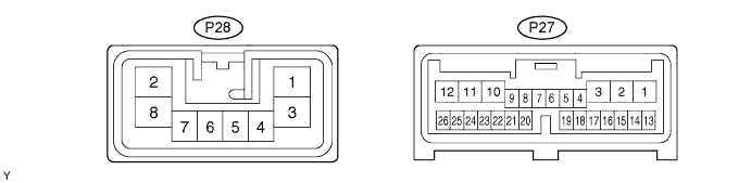
Disconnect the P27 and P28 ECU connectors.

Measure the voltage between the specified terminals on the wire harness side connector.
| Terminal No. (Symbols) | Wiring Color | Terminal Description | Condition | Specified Condition |
| P28-2 (B) - Body ground | B - Body ground | Power supply (Battery) | Always | 11 to 14 V |
| P27-10 (ECUB) - Body ground | W - Body ground | Power supply (Battery) | Always | 11 to 14 V |
Measure the resistance between the specified terminals on the wire harness side connector.
| Terminal No. (Symbols) | Wiring Color | Terminal Description | Condition | Specified Condition |
| P27-22 (MPX1) - Body ground | R - Body ground | MPX line | Always | 10 kΩ or higher |
| P28-8 (GND) - Body ground | W-B - Body ground | Ground | Always | Below 1 Ω |
| POWER SLIDE DOOR ECU LH |
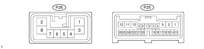
Disconnect the P25 and P26 ECU connectors.

Measure the voltage between the specified terminals on the wire harness side connector.
| Terminal No. (Symbols) | Wiring Color | Terminal Description | Condition | Specified Condition |
| P26-2 (B) - Body ground | B-W - Body ground | Power supply (Battery) | Always | 11 to 14 V |
| P25-10 (ECUB) - Body ground | W - Body ground | Power supply (Battery) | Always | 11 to 14 V |
Measure the resistance between the specified terminals on the wire harness side connector.
| Terminal No. (Symbols) | Wiring Color | Terminal Description | Condition | Specified Condition |
| P25-22 (MPX1) - Body ground | R - Body ground | MPX line | Always | 10 kΩ or higher |
| P26-8 (GND) - Body ground | W-B - Body ground | Ground | Always | Below 1 Ω |
| POWER BACK DOOR ECU |
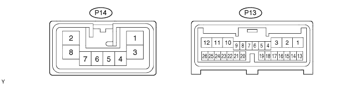
Disconnect the P13 and P14 ECU connectors.

Measure the voltage between the specified terminals on the wire harness side connector.
| Terminal No. (Symbols) | Wiring Color | Terminal Description | Condition | Specified Condition |
| P14-2 (B) - Body ground | B-R - Body ground | Power supply (Battery) | Always | 11 to 14 V |
| P13-10 (ECUB) - Body ground | W-L - Body ground | Power supply (Battery) | Always | 11 to 14 V |
| P13-9 (IG) - Body ground | B-R - Body ground | Power supply (IG) | Ignition switch: ON | 11 to 14 V |
Measure the resistance between the specified terminals on the wire harness side connector.
| Terminal No. (Symbols) | Wiring Color | Terminal Description | Condition | Specified Condition |
| P13-22 (MPX1) - Body ground | R-L - Body ground | MPX line | Always | 10 kΩ or higher |
| P14-8 (GND) - Body ground | W-B - Body ground | Ground | Always | Below 1 Ω |
| OUTER MIRROR CONTROL ECU RH (with Driving Position Memory) |
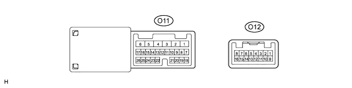
Disconnect the O11 ECU connector.

Measure the voltage between the specified terminals on the wire harness side connector.
| Terminal No. (Symbols) | Wiring Color | Terminal Description | Condition | Specified Condition |
| O11-3 (SIG) - Body ground | B-R - Body ground | Power supply (IG) | Ignition switch: ON | 11 to 14 V |
| O11-4 (CPUB) - Body ground | W-L - Body ground | Power supply (Battery) | Always | 11 to 14 V |
| O11-6 (BDR) - Body ground | R-L - Body ground | Power supply (Battery) | Always | 11 to 14 V |
Measure the resistance between the specified terminals on the wire harness side connector.
| Terminal No. (Symbols) | Wiring Color | Terminal Description | Condition | Specified Condition |
| O11-8 (MPX1) - Body ground | R-L - Body ground | MPX line | Always | 10 kΩ or higher |
| O11-1 (GND) - Body ground | W-B - Body ground | Ground | Always | Below 1 Ω |
| OUTER MIRROR CONTROL ECU LH (with Driving Position Memory) |
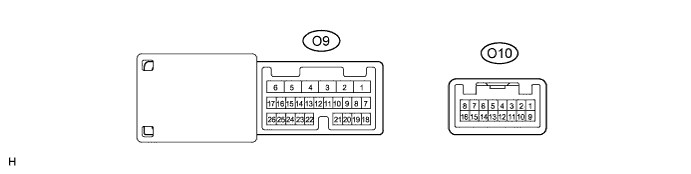
Disconnect the O9 ECU connector.

Measure the voltage between the specified terminals on the wire harness side connector.
| Terminal No. (Symbols) | Wiring Color | Terminal Description | Condition | Specified Condition |
| O9-3 (SIG) - Body ground | B-R - Body ground | Power supply (IG) | Ignition switch: ON | 11 to 14 V |
| O9-4 (CPUB) - Body ground | W-L - Body ground | Power supply (Battery) | Always | 11 to 14 V |
| O9-6 (BDR) - Body ground | R-L - Body ground | Power supply (Battery) | Always | 11 to 14 V |
Measure the resistance between the specified terminals on the wire harness side connector.
| Terminal No. (Symbols) | Wiring Color | Terminal Description | Condition | Specified Condition |
| O9-8 (MPX1) - Body ground | R-L - Body ground | MPX line | Always | 10 kΩ or higher |
| O9-1 (GND) - Body ground | W-B - Body ground | Ground | Always | Below 1 Ω |