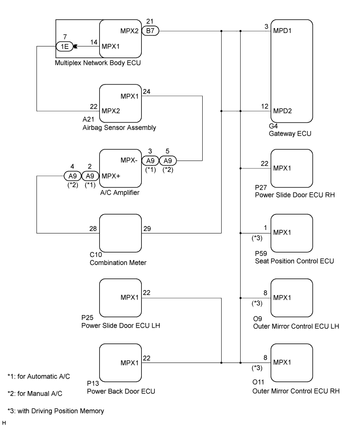
DTC B1214 Short to B+ in Door System Communication Bus Malfunction |
DTC B1215 Short to GND in Door System Communication Bus Malfunction |
| DTC No. | DTC Detection Condition | Trouble Area |
| B1214 | Communication circuit and +B battery system short |
|
| B1215 | Communication circuit and body ground short |
|
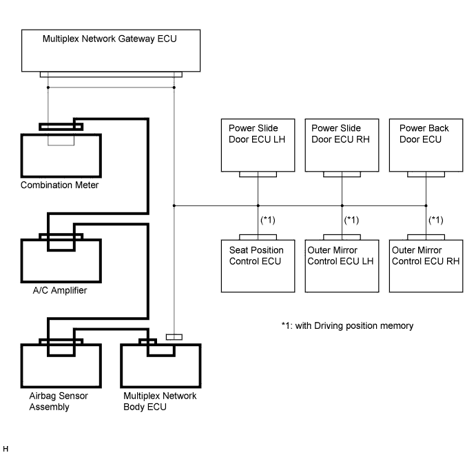
| 1.CHECK DTC (MULTIPLEX NETWORK BODY ECU - COMBINATION METER) |
Check the DTC when the B7 connector of the multiplex network body ECU and the combination meter connector are disconnected.
|
| ||||
| OK | |
 |
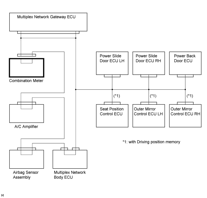
| 2.CHECK DTC (COMBINATION METER) |
Check whether the output of the DTC stops when the combination meter connector is disconnected.
|
| ||||
| NG | |
|
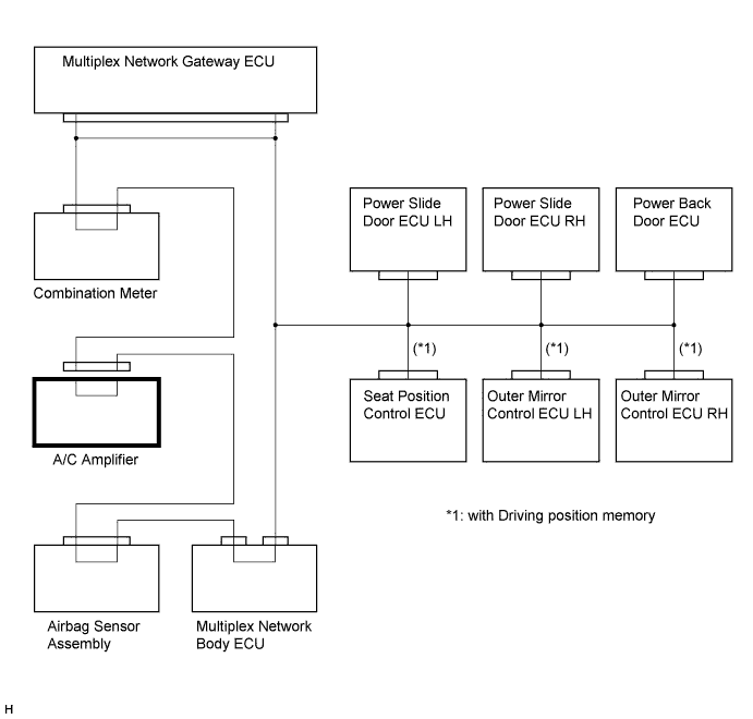
| 3.CHECK DTC (A/C AMPLIFIER) |
Check whether the output of the DTC stops when the A/C amplifier connector is disconnected.
|
| ||||
| NG | |
|
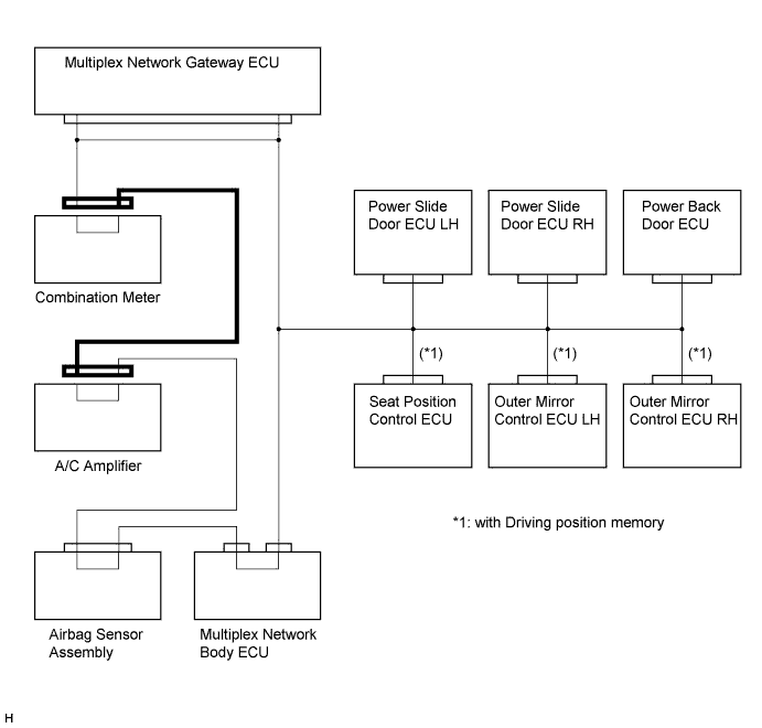
| 4.CHECK HARNESS AND CONNECTOR (COMBINATION METER - A/C AMPLIFIER) |
Check whether the output of the DTC stops when the combination meter connector and the A/C amplifier connector are disconnected.
|
| ||||
| NG | |
|
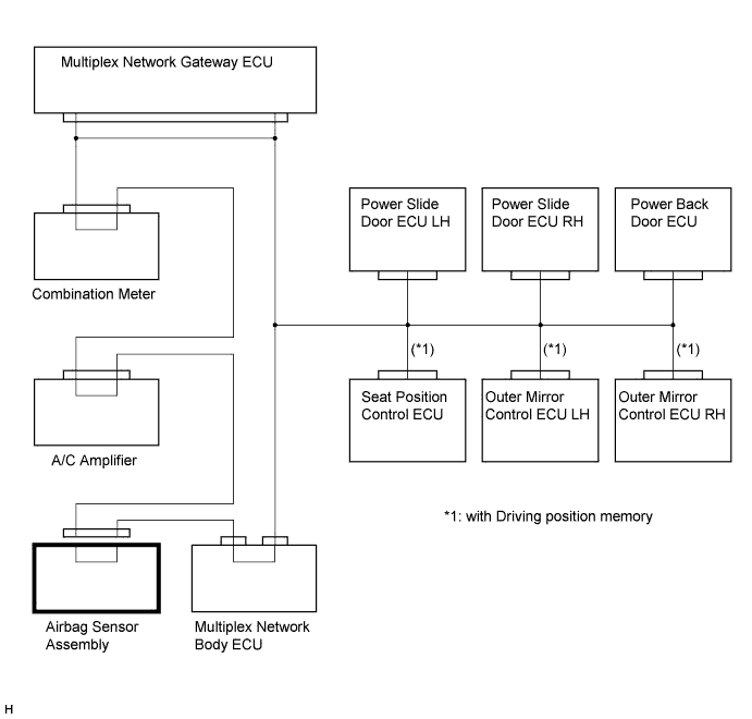
| 5.CHECK DTC (AIRBAG SENSOR ASSEMBLY) |
Check whether the output of the DTC stops when the airbag sensor assembly connector is disconnected.
|
| ||||
| NG | |
|
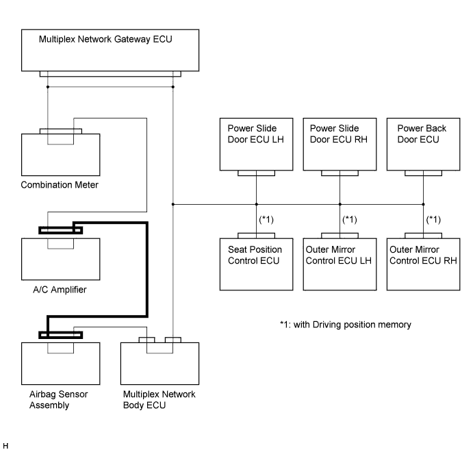
| 6.CHECK HARNESS AND CONNECTOR (A/C AMPLIFIER - AIRBAG SENSOR ASSEMBLY) |
Check whether the output of the DTC stops when the A/C amplifier connector and the airbag sensor assembly connector are disconnected.
|
| ||||
| NG | |
|
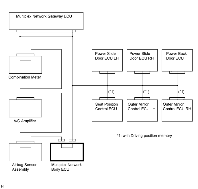
| 7.CHECK DTC (MULTIPLEX NETWORK BODY ECU) |
Check whether the output of the DTC stops when the B7 and 1E connectors of the multiplex network body ECU are disconnected.
|
| ||||
| NG | ||
 | ||
| ||
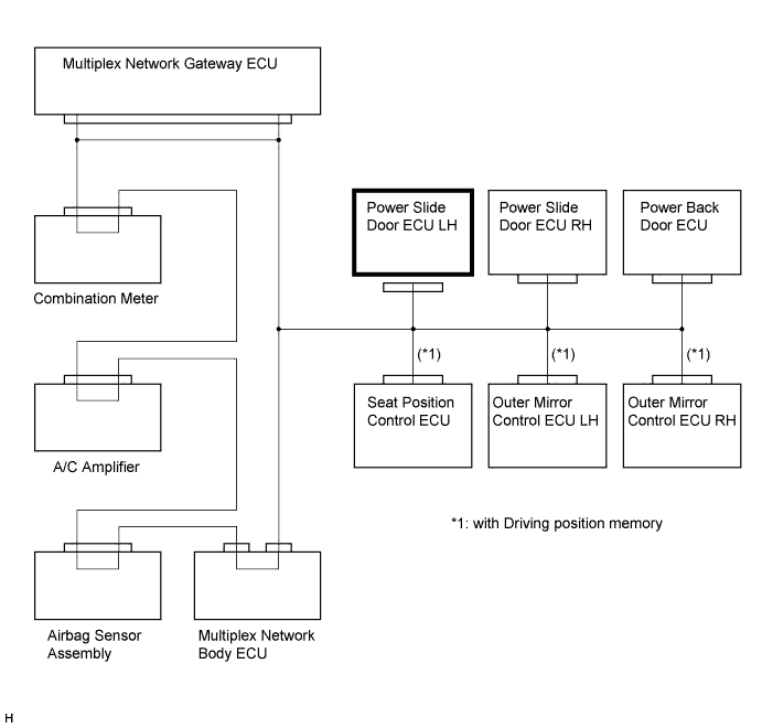
| 8.CHECK DTC (POWER SLIDE DOOR ECU LH) |
Check whether the output of the DTC stops when the power slide door ECU LH connector is disconnected.
|
| ||||
| NG | |
|
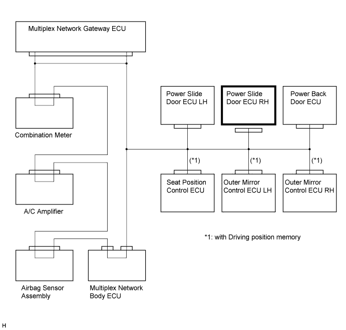
| 9.CHECK DTC (POWER SLIDE DOOR ECU RH) |
Check whether the output of the DTC stops when the power slide door ECU RH connector is disconnected.
|
| ||||
| NG | |
|
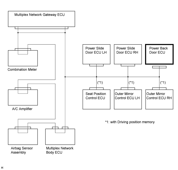
| 10.CHECK DTC (POWER BACK DOOR ECU) |
Check whether the output of the DTC stops when the power back door ECU connector is disconnected.
|
| ||||
| NG | |
|
| 11.CONFIRM MODEL |
| Result | Proceed to |
| with Driving position memory | A |
| without Driving position memory | B |
|
| ||||
| A | |
|
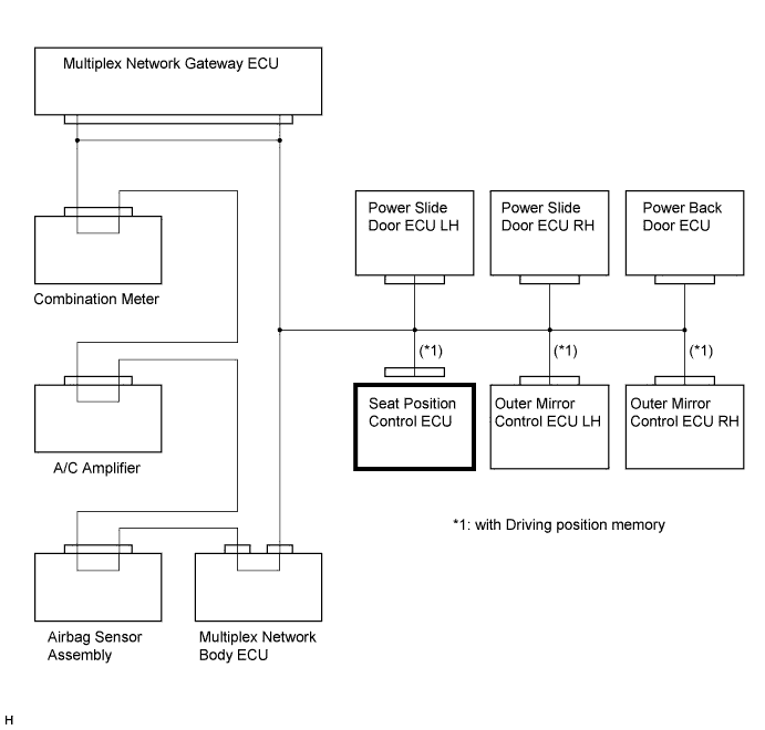
| 12.CHECK DTC (SEAT POSITION CONTROL ECU) |
Check whether the output of the DTC stops when the seat position control ECU connector is disconnected.
|
| ||||
| NG | |
|
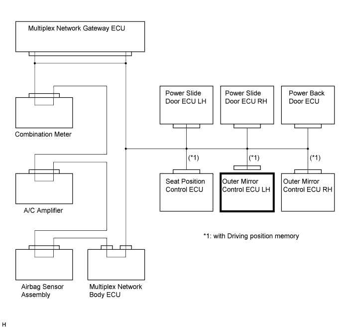
| 13.CHECK DTC (OUTER MIRROR CONTROL ECU LH) |
Check whether the output of the DTC stops when the outer mirror control ECU LH connector is disconnected.
|
| ||||
| NG | |
|
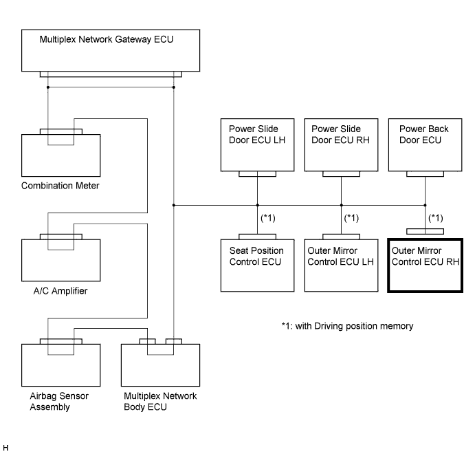
| 14.CHECK DTC (OUTER MIRROR CONTROL ECU RH) |
Check whether the output of the DTC stops when the outer mirror control ECU RH connector is disconnected.
|
| ||||
| NG | |
|
| 15.CHECK HARNESS AND CONNECTOR |
Check for a short to +B or body ground.
Disconnect the multiplex network gateway ECU, combination meter, power slide door ECU LH, power slide door ECU RH, power back door ECU, seat position control ECU (*1), outer mirror control ECU LH (*1), outer mirror control ECU RH (*1) and the B7 connector of the multiplex network body ECU.
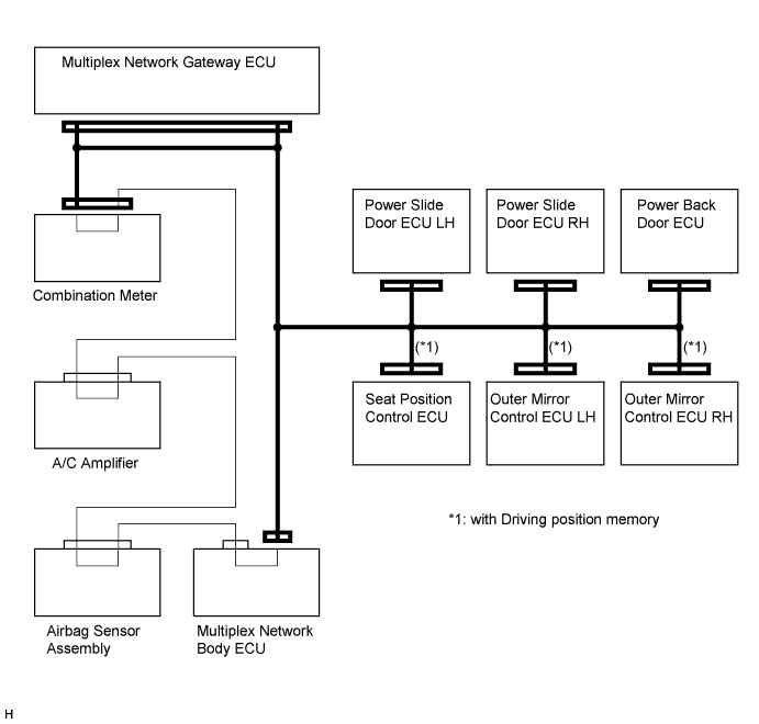
Measure the voltage according to the value(s) in the table below.
| Tester Connection | Condition | Specified Condition |
| Combination meter connector / Multiplex network gateway ECU connector - Body ground | Always | Below 1 V |
| Multiplex network body ECU connector / Multiplex network gateway ECU connector - Body ground | Always | Below 1 V |
| Power slide door ECU LH connector / Multiplex network gateway ECU connector - Body ground | Always | Below 1 V |
| Power slide door ECU RH connector / Multiplex network gateway ECU connector - Body ground | Always | Below 1 V |
| Power back door ECU connector / Multiplex network gateway ECU connector - Body ground | Always | Below 1 V |
| Seat position control ECU connector / Multiplex network gateway ECU connector - Body ground (*1) | Always | Below 1 V |
| Outer mirror control ECU LH connector / Multiplex network gateway ECU connector - Body ground (*1) | Always | Below 1 V |
| Outer mirror control ECU RH connector / Multiplex network gateway ECU connector - Body ground (*1) | Always | Below 1 V |
| Multiplex network body ECU connector / Combination meter connector - Body ground | Always | Below 1 V |
Measure the resistance according to the value(s) in the table below.
| Tester Connection | Condition | Specified Condition |
| Combination meter connector / Multiplex network gateway ECU connector - Body ground | Always | 10 kΩ or higher |
| Multiplex network body ECU connector / Multiplex network gateway ECU connector - Body ground | Always | 10 kΩ or higher |
| Power slide door ECU LH connector / Multiplex network gateway ECU connector - Body ground | Always | 10 kΩ or higher |
| Power slide door ECU RH connector / Multiplex network gateway ECU connector - Body ground | Always | 10 kΩ or higher |
| Power back door ECU connector / Multiplex network gateway ECU connector - Body ground | Always | 10 kΩ or higher |
| Seat position control ECU connector / Multiplex network gateway ECU connector - Body ground (*1) | Always | 10 kΩ or higher |
| Outer mirror control ECU LH connector / Multiplex network gateway ECU connector - Body ground (*1) | Always | 10 kΩ or higher |
| Outer mirror control ECU RH connector / Multiplex network gateway ECU connector - Body ground (*1) | Always | 10 kΩ or higher |
| Multiplex network body ECU connector / Combination meter connector - Body ground | Always | 10 kΩ or higher |
|
| ||||
| OK | ||
| ||
| ||

