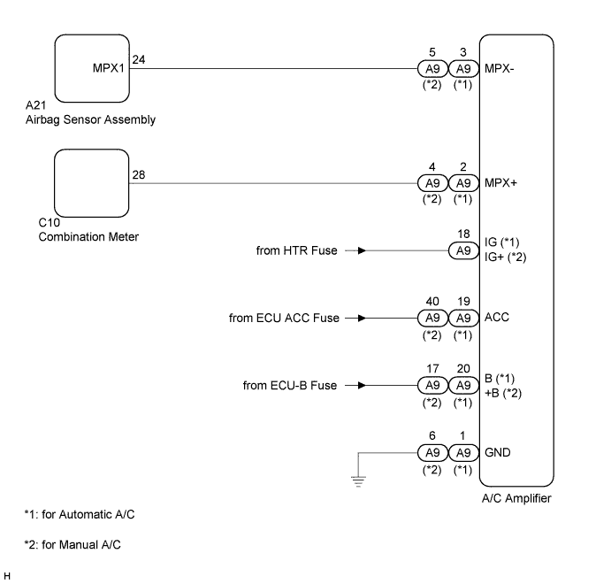
DTC B1262 A/C ECU Communication Stop |
| DTC No. | DTC Detection Condition | Trouble Area |
| B1262 | A/C ECU communication stops |
|
| 1.CHECK HARNESS AND CONNECTOR (A/C AMPLIFIER - BATTERY) |
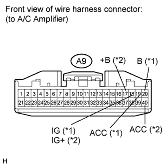 |
Disconnect the A9 connector.
Measure the voltage according to the value(s) in the table below.
| Tester Connection | Condition | Specified Condition |
| A9-18 (IG) (*1), (IG+) (*2) - Body ground | Ignition switch: ON | 11 to 14 V |
| A9-19 (ACC) (*1), A9-40 (ACC) (*2) - Body ground | Ignition switch: ACC | 11 to 14 V |
| A9-20 (B) (*1), A9-17 (+B) (*2) - Body ground | Always | 11 to 14 V |
|
| ||||
| OK | |
 |
| 2.CHECK HARNESS AND CONNECTOR (A/C AMPLIFIER - GROUND) |
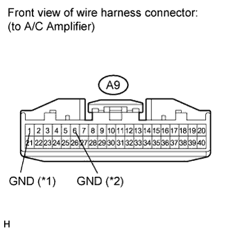 |
Measure the resistance according to the value(s) in the table below.
| Tester Connection | Condition | Specified Condition |
| A9-1 (GND) (*1), A9-6 (GND) (*2) - Body ground | Always | Below 1 Ω |
|
| ||||
| OK | |
|
| 3.CHECK COMMUNICATION LINE |
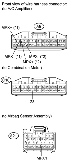 |
Disconnect the C10 and A21 connectors.
Measure the resistance according to the value(s) in the table below.
| Tester Connection | Condition | Specified Condition |
| A9-3 (MPX-) (*1), A9-5 (MPX-) (*2) - A21-24 (MPX1) | Always | Below 1 Ω |
| A9-2 (MPX+) (*1), A9-4 (MPX+) (*2) - C10-28 | Always | Below 1 Ω |
| Result | Proceed to |
| Both are OK | A |
| One is OK | B |
| Both are NG | C |
|
| ||||
|
| ||||
| A | ||
 | ||
| ||
