 |
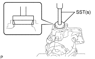
Using SST(s) and a press, install the transfer driven pinion rear bearing outer race to the transfer case.
- SST
- 09950-60010
(09951-00620)
09950-70010 (09951-07150)
- NOTICE:
- Place something like wood blocks under the case to keep its level.
TRANSFER UNIT > REASSEMBLY |
| 1. INSTALL TRANSFER DRIVEN PINION REAR BEARING |
|
Using SST(s) and a press, install the transfer driven pinion rear bearing outer race to the transfer case.
| 2. INSTALL TRANSFER OUTPUT SHAFT WASHER |
Install the transfer output washer to the transfer case.
| 3. INSTALL TRANSFER DRIVEN PINION FRONT BEARING |
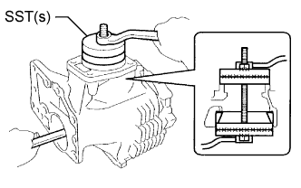 |
Install the transfer driven pinion front bearing outer race to the transfer case with SST(s), bolt and nut.
| 4. INSTALL RING GEAR MOUNTING CASE PLATE WASHER |
Install the ring gear mounting case plate washer to the transfer case.
| 5. INSTALL CENTER DIFFERENTIAL CASE TAPERED ROLLER BEARING |
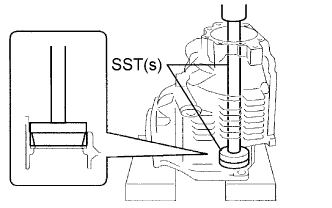 |
Using SST(s) and a press, install the center differential case tapered roller bearing LH outer race to the transfer case.
| 6. INSTALL TRANSFER DRIVEN PINION FRONT BEARING |
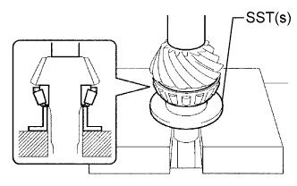 |
Using SST(s) and a press, install the transfer driven pinion front bearing inner race to the driven pinion.
| 7. INSTALL DRIVEN PINION |
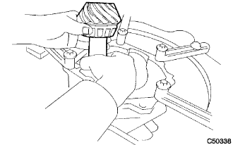 |
Install the driven pinion to the transfer case.
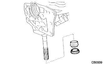 |
Install a new transfer pinion bearing spacer and anew transfer driven pinion rear bearing inner race to the driven pinion.
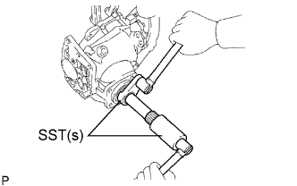 |
Using SST(s), tighten a new transfer gear nut (at a standard torque.)
| 8. INSPECT AND ADJUST DRIVEN PINION PRELOAD |
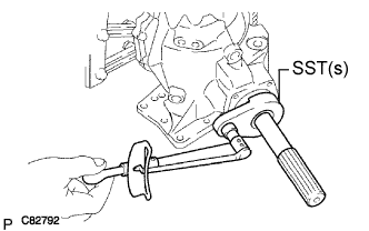 |
Using SST(s) and a torque wrench, measure thee initial torque of the driven pinion.
If the preload is too large, replace the transfer pinion bearing spacer with a new one.
If the preload is too small, repeatedly adjust the preload by tightening the transfer gear nut 5 to 10 degrees at a time until the standard value is obtained.
If the preload is insufficient, even though the tightening torque of the transfer gear nut exceeds the maximum of the standard value., loosen the transfer gear nut and apply gear oil SAE 90 (GL-5) to the transfer gear nut and the screw thread and the base of driven pinion. And then repeat the preceding operation . If the tightening torque is bearing spacer with anew one and adjust it.
| 9. INSTALL RING GEAR |
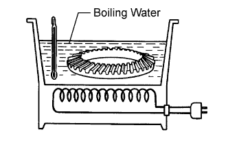 |
Heat the ring gear in boiling water from 90 to 100 °C (194 to 212 °F).
Completely remove grease and moisture on the contact surfaces of the ring gear and the transfer ring gear mounting case.
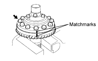 |
Align the matchmarks on the ring gear and transfer ring gear mounting case and quickly assemble them.
Tighten the 12 bolts.
| 10. INSTALL CENTER DIFFERENTIAL CASE TAPERED ROLLER BEARING |
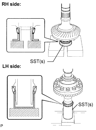 |
Using SST(s) and a press, install the inner race of the center differential case tapered roller bearing to the transfer ring gear mounting case.
| 11. INSTALL TRANSFER RING GEAR MOUNTING CASE |
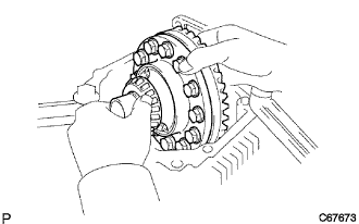 |
Install the transfer ring gear mounting case to the transfer case.
| 12. INSTALL NO. 2 TRANSFER RING GEAR MOUNTING CASE WASHER |
Install the No. 2 transfer ring gear mounting case washer to the transfer RH bearing retainer sub-assembly.
| 13. INSTALL CENTER DIFFERENTIAL CASE TAPERED ROLLER BEARING |
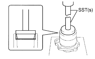 |
Using SST(s) and a press, install the center differential case tapered roller bearing RH outer race to the transfer RH bearing retainer sub-assembly.
| 14. INSTALL TRANSFER RH BEARING RETAINER SUB-ASSEMBLY |
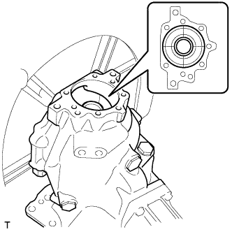 |
Place the transfer with the surface where the transfer RH bearing retainer sub-assembly is facing up.
Align the centers of the transfer ring gear mounting case and the transfer case.
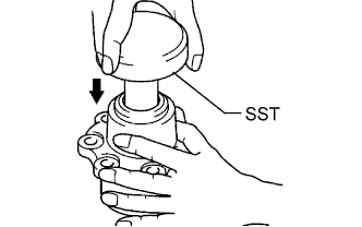 |
Insert SST into the transfer RH bearing retainer sub-assembly.
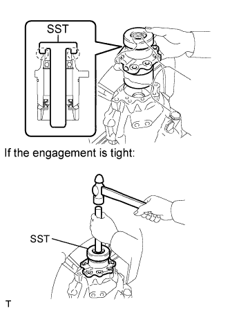 |
With SST and the transfer RH bearing sub-assembly in close contact, install the transfer RH bearing retainer sub-assembly together with SST into the transfer case.
Make sure that the transfer RH bearing retainer sub-assembly and transfer case contact closely.
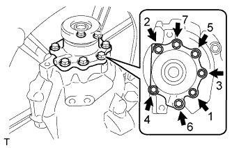 |
Tighten the 7 bolts evenly in order shown in the illustration.
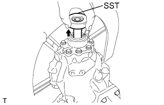 |
Remove the SST.
| 15. INSPECT DIFFERENTIAL RING GEAR BACKLASH |
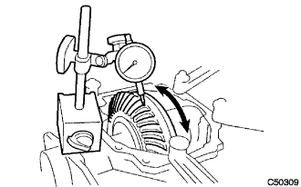 |
Set the dial gauge perpendicular to the ring gear face, fix the driven pinion, and check backlash by moving the ring gear.
If the measured value is out of standard, select a proper washer for the center differential case tapered roller bearing on the LH side from the table below and install it to obtain the standard value.
| Mark | Washer Thickness mm (in.) | Mark | Washer Thickness mm (in.) | Mark | Washer Thickness mm (in.) |
| AA | 2.07 (0.0814) | AB | 2.10 (0.0826) | AC | 2.13 (0.0838) |
| BA | 2.16 (0.0850) | BB | 2.19 (0.0862) | BC | 2.22 (0.0874) |
| CA | 2.25 (0.0885) | CB | 2.28 (0.0897) | CC | 2.31 (0.0909) |
| DA | 2.34 (0.0921) | DB | 2.37 (0.0933) | DC | 2.40 (0.0944) |
| EA | 2.43 (0.0956) | EB | 2.46 (0.0968) | EC | 2.49 (0.0980) |
| FA | 2.52 (0.0992) | FB | 2.55 (0.1003) | FC | 2.58 (0.1015) |
| GA | 2.61 (0.1027) | GB | 2.64 (0.1039) | GC | 2.67 (0.1051) |
| HA | 2.70 (0.1062) | HB | 2.73 (0.1074) | HC | 2.76 (0.1086) |
| JA | 2.79 (0.1098) | JB | 2.82 (0.1110) | JC | 2.85 (0.1122) |
| KA | 2.88 (0.1133) | KB | 2.91 (0.1145) | KC | 2.94 (0.1157) |
| LA | 2.97 (0.1169) | LB | 3.00 (0.1181) |
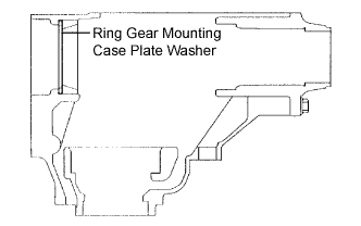 |
Ring gear mounting case plate washer location is shown in the illustration.
| 16. INSPECT TOOTH CONTACT BETWEEN RING GEAR AND DRIVE PINION |
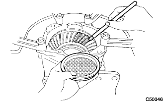 |
Apply red lead primer thinly and uniformly to both faces of the ring gear and rotate it several times.
Observe the pattern shown by red lead primer.
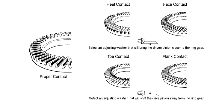
In case of poor tooth contact, select a washer for the driven pinion bearing front side from the following table and replace it.
| Mark | Washer Thickness mm (in.) | Mark | Washer Thickness mm (in.) | Mark | Washer Thickness mm (in.) |
| AA | 1.20 (0.0472) | AC | 1.22 (0.0480) | BB | 1.24 (0.0488) |
| CA | 1.26 (0.0496) | CC | 1.28 (0.0503) | DB | 1.30 (0.0511) |
| EA | 1.32 (0.0519) | EC | 1.34 (0.0527) | FB | 1.36 (0.0535) |
| GA | 1.38 (0.0543) | GC | 1.40 (0.0551) | HB | 1.42 (0.0559) |
| JA | 1.44 (0.0566) | JC | 1.46 (0.0574) | KB | 1.48 (0.0582) |
| LA | 1.50 (0.0590) | LC | 1.52 (0.0598) | MB | 1.54 (0.0606) |
| NA | 1.56 (0.0614) | NC | 1.58 (0.0622) | PB | 1.60 (0.0629) |
| QA | 1.62 (0.0637) | QC | 1.64 (0.0645) |
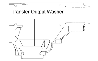 |
The location of the transfer output washer for tooth contact adjustment is shown in the illustration.
| 17. ADJUST TOTAL PRELOAD |
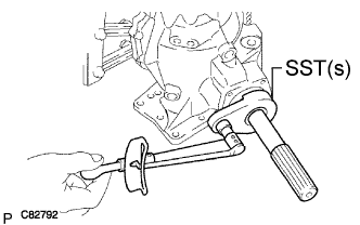 |
Using SST(s) and a torque wrench, measure the initial torque with the driven pinion bearing contact with the ring gear face.
If the value is out of standard range, select the washer for the center differential case tapered roller bearing RH side from the following table and replace it.
| Mark | Washer Thickness mm (in.) | Mark | Washer Thickness mm (in.) | Mark | Washer Thickness mm (in.) |
| AA | 1.47 (0.0578) | AB | 1.50 (0.0590) | AC | 1.53 (0.0602) |
| BA | 1.56 (0.0614) | BB | 1.59 (0.0625) | BC | 1.62 (0.0637) |
| CA | 1.65 (0.0649) | CB | 1.68 (0.0661) | CC | 1.71 (0.0673) |
| DA | 1.74 (0.0685) | DB | 1.77 (0.0696) | DC | 1.80 (0.0708) |
| EA | 1.83 (0.0720) | EB | 1.86 (0.0732) | EC | 1.89 (0.0744) |
| FA | 1.92 (0.0755) | FB | 1.95 (0.0767) | FC | 1.98 (0.0779) |
| GA | 2.01 (0.0790) | GB | 2.04 (0.0803) | GC | 2.07 (0.0814) |
| HA | 2.10 (0.0826) | HB | 2.13 (0.0838) | HC | 2.16 (0.0850) |
| JA | 2.19 (0.0862) | JB | 2.22 (0.0874) | JC | 2.25 (0.0885) |
| KA | 2.28 (0.0897) | KB | 2.31 (0.0909) | KC | 2.34 (0.0921) |
| LA | 2.37 (0.0933) | LB | 2.40 (0.0944) | LC | 2.43 (0.0956) |
| MA | 2.46 (0.0968) | MB | 2.49 (0.0980) | MC | 2.52 (0.0992) |
| NA | 2.55 (0.1003) | NB | 2.58 (0.1015) |
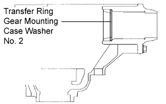 |
The location of the transfer ring gear mounting case washer No. 2 for preload adjustment is show in the illustration.
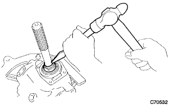 |
Using a chisel, stake the transfer gear nut.
| 18. REMOVE TRANSFER RH BEARING RETAINER SUB-ASSEMBLY |
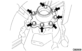 |
Remove the 7 bolts from the transfer RH bearing retainer sub-assembly.
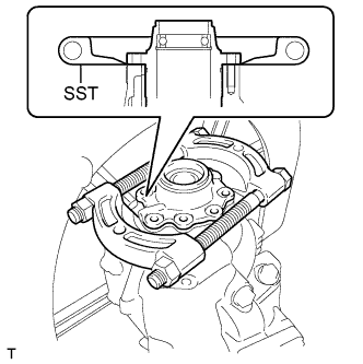 |
Using SST, make a clearance between the transfer RH bearing retainer sub-assembly and the transfer case.
Remove the SST.
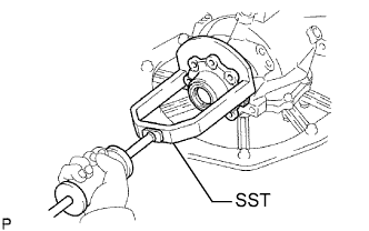 |
Using SST, remove the transfer RH bearing retainer sub-assembly from the transfer case.
| 19. REMOVE CENTER DIFFERENTIAL CASE TAPERED ROLLER BEARING |
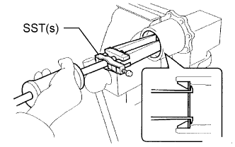 |
Fix the transfer RH bearing retainer sub-assembly in a vise.
Using SST(s), remove the center differential case tapered roller bearing RH outer race and transfer ring gear mounting case washer No. 2 from the transfer RH bearing retainer sub-assembly.
| 20. INSTALL SIDE GEAR SHAFT HOLDER BEARING |
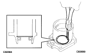 |
Install the side gear shaft holder bearing to the transfer RH bearing retainer sub-assembly.
Using snap ring pliers, install the side gear shaft holder hole snap ring.
| 21. INSTALL TRANSFER RH BEARING RETAINER OIL SEAL |
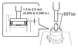 |
Using SST(s) and a press, install the transfer RH bearing retainer oil seal No. 2 to the transfer RH bearing retainer sub-assembly.
Apply small amount of MP grease No. 2 to the oil seal lip.
| 22. INSTALL NO. 2 TRANSFER RING GEAR MOUNTING CASE WASHER |
Install the No. 2 selected transfer ring gear mounting washer to the transfer RH bearing retainer sub-assembly.
| 23. INSTALL CENTER DIFFERENTIAL CASE TAPERED ROLLER BEARING |
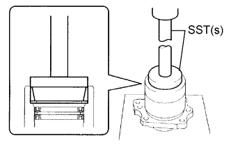 |
Using SST(s) and a press, install the center differential case tapered roller bearing RH outer race to the transfer RH bearing retainer sub-assembly.
| 24. INSTALL O-RING |
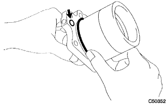 |
Coat the 2 O-rings with hypoid gear oil.
Install the 2 O-rings to the transfer RH bearing retainer sub-assembly.
| 25. INSTALL TRANSFER RH BEARING RETAINER SUB-ASSEMBLY |
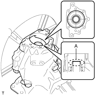 |
Place the transfer with the surface where the transfer RH bearing retainer sub-assembly is facing up.
Align the centers of the transfer ring gear mounting case and the transfer case.
Apply MP grease No. 2 thinly to area A as shown in the illustration.
|
Insert SST into the transfer RH bearing retainer sub-assembly.
|
With SST and the transfer RH bearing sub-assembly in close contact, install the transfer RH bearing retainer sub-assembly together with SST into the transfer case.
Make sure that the transfer RH bearing retainer sub-assembly and transfer case contact closely.
|
Tighten the 7 bolts evenly in order shown in the illustration.
|
Remove the SST.
| 26. INSPECT TOTAL PRELOAD |
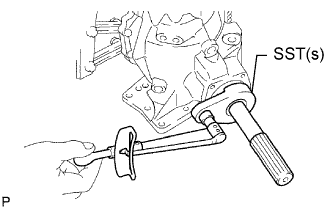 |
Using SST(s) and a torque wrench, measure the initial torque with the driven pinion being in contact with the ring gear face.
| 27. INSTALL TRANSFER RH BEARING RETAINER OIL SEAL |
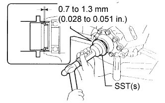 |
Using SST(s), install the transfer RH bearing retainer oil seal to the transfer RH bearing retainer sub-assembly to the position as shown in the illustration.
Apply MP grease to the oil seal lip.
| 28. INSTALL TRANSFER CASE OIL SEAL |
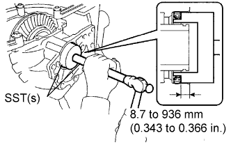 |
Using(s), install the transfer case oil seal to the transfer case at the position as shown in the illustration.
Apply small amount of MP grease to the oil seal lip.
| 29. INSTALL CTR DIFFERENTIAL LOCK SLEEVE |
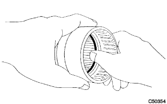 |
Coat a new O-ring with hypoid gear oil.
Install the O-ring to the CTR differential lock sleeve.
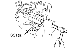 |
Using SST(s), install the CTR differential lock sleeve to the transfer case.
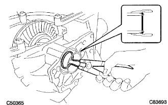 |
Using snap ring pliers, install the shaft snap ring.
| 30. INSTALL TRANSFER EXTENSION HOUSING TYPE T OIL SEAL |
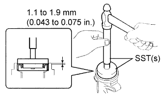 |
Using SST(s), install the transfer extension housing type T oil seal to the transfer extension housing at the position as shown in the illustration.
Apply small amount of MP grease No. 2 to the oil seal lip.
| 31. INSTALL TRANSFER EXTENSION HOUSING DUST DEFLECTOR |
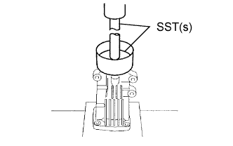 |
Using SST(s) and press, install a new transfer extension housing dust deflector to the transfer extension housing sub-assembly.
| 32. INSTALL TRANSFER EXTENSION HOUSING SUB-ASSEMBLY |
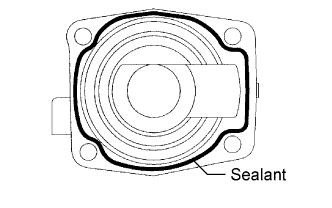 |
Apply FIPG to the transfer extension housing sub-assembly in continuous beaded from of 1.2 mm diameter as show in the illustration.
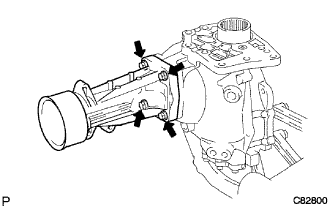 |
Install the transfer extension housing sub-assembly to the transfer case with the 4 bolts.
Remove the transfer assembly from the overhaul attachment.
| 33. INSTALL TRANSFER AND TRANSAXLE SETTING STUD BOLT |
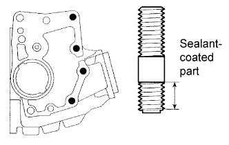 |
Install the transfer and transaxle setting stud bolts to the parts of the transfer case as show in the illustration.
| 34. INSTALL TRANSFER CASE STRAIGHT PIN |
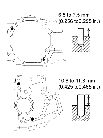 |
Using a plastic hammer, install the transfer case straight pins to the transfer case as shown in thee illustration.
| 35. INSTALL TRANSFER DYNAMIC DAMPER |
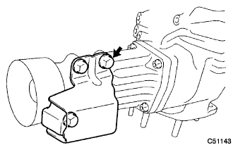 |
Install the transfer dynamic damper to the transfer extension housing sub-assembly with the 3 bolts.
| 36. INSTALL BREATHER OIL DEFLECTOR |
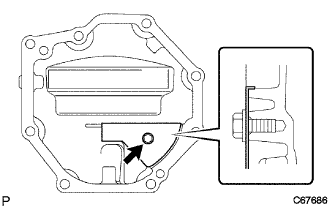 |
Install the breather oil deflector to the transfer case cover No. 1 with the bolt.
| 37. INSTALL NO. 1 TRANSFER CASE COVER |
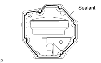 |
Apply FIPG to the transfer case cover No. 1 in a continuous bead of 1.2 mm diameter as show in the illustration.
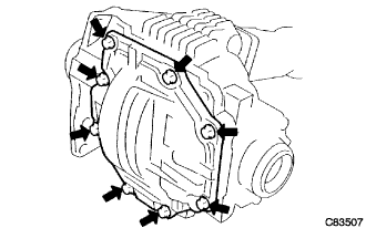 |
Install the transfer case cover No. 1 to the transfer case with 8 bolts.
| 38. INSTALL TRANSFER CASE BREATHER PLUG |
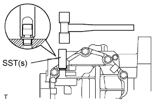 |
Using SST(s) and a hammer, install the transfer case breather plug to the transfer case cover No. 1.
| 39. INSTALL TRANSFER COVER GASKET |
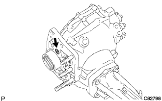 |
Install a new transfer cover gasket to the transfer case.