 |
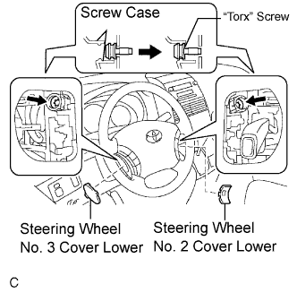
Using a "torx" socket wrench (T30), loosen the 2 "torx" screws until the groove along the screw circumference catches on the screw case.
STEERING COLUMN ASSEMBLY > REMOVAL |
| 1. PRECAUTION |
| 2. ALIGN FRONT WHEELS FACING STRAIGHT AHEAD |
| 3. DISCONNECT BATTERY NEGATIVE TERMINAL |
| 4. REMOVE STEERING WHEEL COVER LOWER NO.2 |
Using a screwdriver, remove the steering wheel No.2 cover lower.
| 5. REMOVE STEERING WHEEL COVER LOWER NO.3 |
Using a screwdriver, remove the steering wheel No.3 cover lower.
| 6. REMOVE HORN BUTTON ASSEMBLY |
|
Using a "torx" socket wrench (T30), loosen the 2 "torx" screws until the groove along the screw circumference catches on the screw case.
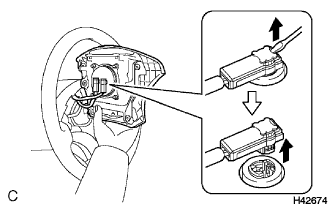 |
Pull out the steering pad from the steering wheel assembly and support the steering pad with one hand as shown in the illustration.
Disconnect the horn connector.
Disconnect the 2 connectors from the steering pad.
Remove the steering pad.
| 7. REMOVE STEERING WHEEL ASSEMBLY |
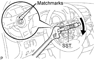 |
Remove the steering wheel assembly set nut.
Put matchmarks on the steering wheel assembly and main shaft assembly.
Using SST, remove the steering wheel assembly.
| 8. REMOVE STEERING COLUMN COVER |
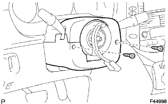 |
Remove the 2 screws and steering column cover.
| 9. REMOVE SPIRAL CABLE SUB-ASSEMBLY |
Disconnect the connectors from the spiral cable.
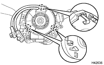 |
Disengage the 3 claws and remove the spiral cable.
| 10. REMOVE HEADLIGHT DIMMER SWITCH ASSEMBLY |
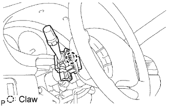 |
Disconnect the connector.
Release the claw fitting and remove the headlight dimmer switch assembly.
| 11. REMOVE WINDSHIELD WIPER SWITCH ASSEMBLY |
Disconnect the connector.
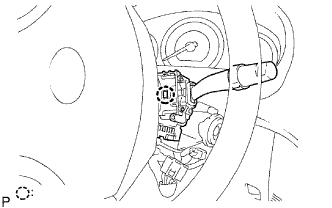 |
Using a screwdriver, disengage the claw and pull out the windshield wiper switch assembly.
| 12. REMOVE FRONT DOOR SCUFF PLATE LH |
| 13. REMOVE COWL SIDE TRIM BOARD LH |
| 14. REMOVE INSTRUMENT PANEL FINISH PANEL SUB-ASSEMBLY LOWER LH |
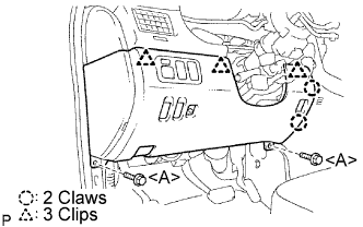 |
Remove the 2 bolts <A>.
Disconnect the hood lock control cable assembly.
Disengage the 2 claws and 3 clips, and then remove the instrument panel finish panel sub-assembly lower LH.
Disconnect the connectors.
| 15. REMOVE INSTRUMENT PANEL SAFETY PAD INSERT SUB-ASSEMBLY NO.1 |
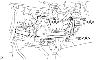 |
Remove the 4 bolts <A> and instrument panel safety pad insert sub-assembly No. 1.
Disconnect the connector.
| 16. REMOVE HEATER TO FOOT DUCT NO.3 |
Disengage the 3 claws and remove the sir duct No. 3.
| 17. SEPARATE STEERING INTERMEDIATE SHAFT ASSEMBLY |
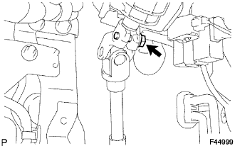 |
Loosen the bolt.
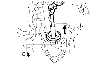 |
Release the 3 clips and separate the dust cover.
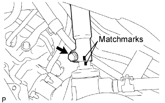 |
Align the matchmarks on the steering intermediate shaft assembly and steering gear assembly.
Remove the bolt and separate the steering intermediate shaft assembly.
| 18. REMOVE STEERING COLUMN ASSEMBLY |
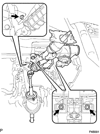 |
Disconnect the connectors and wire harness clamps.
Remove the 3 bolts and steering column assembly from the instrument panel reinforcement assembly.