 |
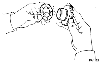
Install the 2 thrust washers to the 2 side gears.
REAR DIFFERENTIAL CARRIER > REASSEMBLY |
| 1. INSTALL REAR DIFFERENTIAL PINION SHAFT |
|
Install the 2 thrust washers to the 2 side gears.
Install the 2 side gears, 2 differential pinion gears, 2 differential pinion thrust washers and differential pinion shaft to the differential case.
| 2. ADJUST DIFFERENTIAL PINION GEAR BACKLASH |
Install the side gear shaft.
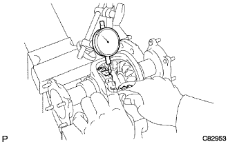 |
Measure the side gear backlash while holding 1 pinion gear toward the differential case.
| Thickness mm (in.) | Thickness mm (in.) |
| 0.93 to 0.97 (0.0366 to 0.0382) | 1.18 to 1.22 (0.0465 to 0.0480) |
| 0.98 to 1.02 (0.0386 to 0.0402) | 1.23 to 1.27 (0.0484 to 0.0500) |
| 1.03 to 1.07 (0.0406 to 0.0421) | 1.28 to 1.32 (0.0504 to 0.0520) |
| 1.08 to 1.12 (0.0425 to 0.0441) | 1.33 to 1.37 (0.0524 to 0.0539) |
| 1.13 to 1.17 (0.0445 to 0.0461) | 1.38 to 1.42 (0.0543 to 0.0559) |
Remove the side gear shaft.
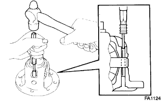 |
Using a pin punch (5 mm) and a hammer, install the straight pin through the differential case and hole of the pinion shaft.
Using a chisel and a hammer, stake the outside of the differential case pin hole.
| 3. INSTALL DIFFERENTIAL RING GEAR |
 |
Clean the contact surfaces of the differential case and ring gear.
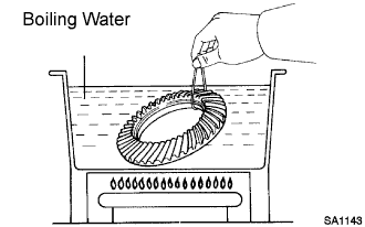
Heat the ring gear to approx. 100°C (212°F) in boiling water.
Carefully take the ring gear out of the boiling water.
After the moisture on the ring gear has completely evaporated, quickly install the ring gear to the differential case.
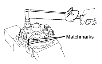 |
Align the matchmarks on the ring gear and differential case.
Temporarily install 4 new lock plates and 8 bolts.
After the ring gear cools down enough, torque the 8 bolts uniformly.
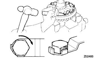 |
Using a chisel and a hammer, stake the 4 lock plates.
Stake one claw so that it is flush against the flat surface of the bolt.
As for the head so as to act as a stopper if the bolt should start to loosen.
| 4. INSTALL REAR DIFFERENTIAL CASE BEARING RH |
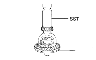 |
Using SST and a press, install the case bearing (RH) to the differential case.
| 5. INSTALL REAR DIFFERENTIAL CASE BEARING LH |
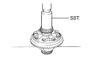 |
Using SST and a press, install the case bearing (LH) to the differential case.
| 6. INSPECT RUNOUT OF DIFFERENTIAL RING GEAR |
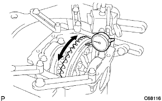 |
Install the differential case to the carrier, and install the 2 plate washers so that there is no play in the bearing.
Install the 2 bearing caps with the 4 bolts
Using a dial gage, measure the runout of the ring gear.
Remove the 2 bearing caps, 2 plate washers and differential carrier.
| 7. INSTALL REAR DRIVE PINION FRONT TAPERED ROLLER BEARING |
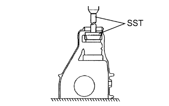 |
Using SST and a press, install the front bearing (outer race) to the carrier.
| 8. INSTALL REAR DRIVE PINION REAR TAPERED ROLLER BEARING |
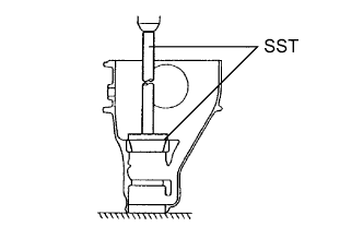 |
Using SST and a press, install the rear bearing (outer race) to the carrier.
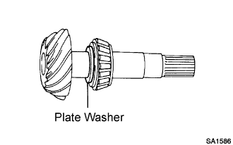
Install the removed plate washer to the drive pinion.
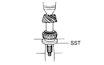 |
Using SST and a press, install the bearing to the drive pinion.
| 9. ADJUST DIFFERENTIAL DRIVE PINION PRELOAD |
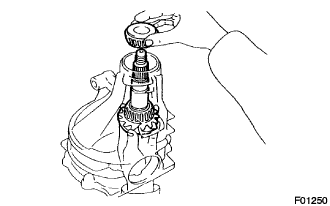 |
Install the drive pinion and front bearing.
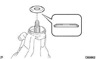 |
Install the oil slinger, as shown in the illustration.
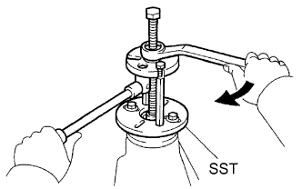 |
Using SST, install the companion flange.
Coat the threads of the nut with hypoid gear oil LSD.
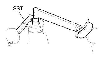 |
Using SST to hold the flange, torque the nut.
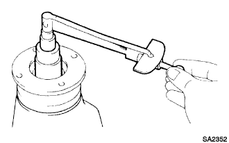 |
Using a torque wrench, measure the preload.
| 10. INSTALL DIFFERENTIAL CASE ASSEMBLY |
Place the 2 bearing outer races on their respective bearings. Make sure the right and left races are not interchanged.
| 11. ADJUST DIFFERENTIAL RING GEAR BACKLASH |
Install the right and left bearing caps with the 4 bolts.
Make sure the differential case bearing and thrust shim by tapping on the ring gear with a plastic hammer.
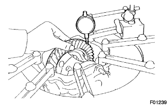 |
Set the dial gauge perpendicular to the end of the ring gear face.
While holding the rear drive pinion companion flange, rotate the ring gear and measure the backlash.
| Thickness mm (in.) | Thickness mm (in.) | Thickness mm (in.) |
| 2.21 to 2.23 (0.0870 to 0.0878) | 2.57 to 2.59 (0.1012 to 0.1020) | 2.93 to 2.95 (0.1154 to 0.1161) |
| 2.24 to 2.26 (0.0882 to 0.0890) | 2.60 to 2.62 (0.1024 to 0.1030) | 2.96 to 2.98 (0.1165 to 0.1173) |
| 2.27 to 2.29 (0.0894 to 0.0902) | 2.63 to 2.65 (0.1035 to 0.1043) | 2.99 to 3.01 (0.1177 to 0.1185) |
| 2.30 to 2.32 (0.0906 to 0.0913) | 2.66 to 2.68 (0.1047 to 0.1055) | 3.02 to 3.04 (0.1189 to 0.1197) |
| 2.33 to 2.35 (0.0917 to 0.0925) | 2.69 to 2.71 (0.1059 to 0.1067) | 3.05 to 3.07(0.1201 to 0.1209) |
| 2.36 to 2.38 (0.0929 to 0.0937) | 2.72 to 2.74 (0.1071 to 0.1079) | 3.08 to 3.10 (0.1213 to 0.1220) |
| 2.39 to 2.41 (0.0941 to 0.0949) | 2.75 to 2.77 (0.1083 to 0.1091) | 3.11 to 3.13 (0.1224 to 0.1232) |
| 2.42 to 2.44 (0.0953 to 0.0961) | 2.78 to 2.80 (0.1094 to 0.1102) | 3.14 to 3.16 (0.1236 to 0.1244) |
| 2.45 to 2.47 (0.0965 to 0.0972) | 2.81 to 2.83 (0.1106 to 0.1114) | 3.17 to 3.19 (0.1248 to 0.1256) |
| 2.48 to 2.50 (0.0976 to 0.0984) | 2.84 to 2.86 (0.1118 to 0.1126) | 3.20 to 3.22 (0.1260 to 0.1268) |
| 2.51 to 2.53 (0.0988 to 0.0996) | 2.87 to 2.89 (0.1130 to 0.1138) | - |
| 2.54 to 2.56 (0.1000 to 0.1008) | 2.90 to 2.92 (0.1142 to 0.1150) | - |
| 12. ADJUST TOTAL PRELOAD |
After adjusting the backlash of the differential ring gear, remove the teeth side thrust shim.
Using a micrometer, measure the thickness of the removed thrust shim.
Select a new thrust shim 0.06 to 0.09 mm (0.0024 to 0.0035 in.) which is thicker than the removed one.
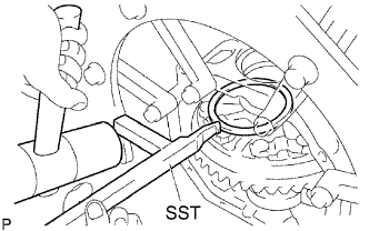 |
Using SST and a plastic hammer, drive in the thrust shim.
Align matchmarks on the bearing cap and differential carrier, and install the 2 bearing caps.
Tighten both bearing caps with the 4 bolts.
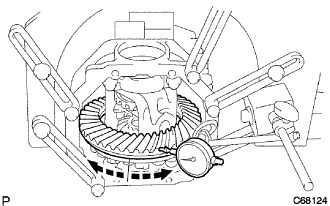 |
Set the dial gauge to the end of the differential ring gear face.
While holding the rear drive pinion companion flange, rotate the differential ring gear and measure the backlash.
If the measured value is out of the specified value, adjust it by increasing or decreasing the thickness of both right and left thrust shims equally.
|
Using a torque wrench, measure the preload.
| 13. INSPECT TOOTH CONTACT BETWEEN RING GEAR AND DRIVE PINION |
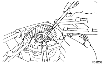 |
Coat 3 or 4 teeth at 3 different positions on the ring gear with red lead primer.
Hold the companion flange firmly and rotate the ring gear in both directions.
Inspection the tooth contact pattern.
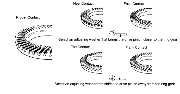
| Thickness mm (in.) | Thickness mm (in.) | Thickness mm (in.) |
| 2.26 to 2.28 (0.0890 to 0.0898) | 2.41 to 2.43 (0.0949 to 0.0957) | 2.56 to 2.58 (0.1008 to 0.1016) |
| 2.29 to 2.31 (0.0902 to 0.0909) | 2.44 to 2.46 (0.0961 to 0.0969) | 2.59 to 2.61 (0.1020 to 0.1028) |
| 2.32 to 2.34 (0.0913 to 0.0921) | 2.47 to 2.49 (0.0972 to 0.0980) | 2.62 to 2.64 (0.1031 to 0.1039) |
| 2.35 to 2.37 (0.0925 to 0.0933) | 2.50 to 2.52 (0.0984 to 0.0992) | 2.65 to 2.67 (0.1043 to 0.1051) |
| 2.38 to 2.40 (0.0937 to 0.0945) | 2.53 to 2.55 (0.0996 to 0.1004) | 2.68 to 2.70 (0.1055 to 0.1063) |
| 14. REMOVE REAR DRIVE PINION NUT |
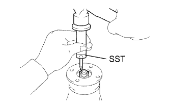 |
Using SST and a hammer, unstake the staked part of the nut.
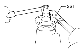 |
Using SST to hold the flange, remove the nut.
| 15. REMOVE REAR DRIVE PINION COMPANION FLANGE SUB-ASSEMBLY |
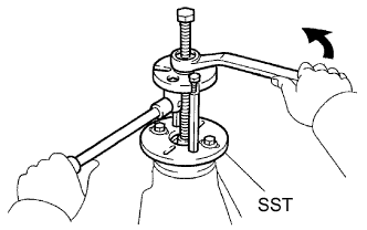 |
Using SST, remove the companion flange.
| 16. REMOVE REAR DIFFERENTIAL DRIVE PINION OIL SLINGER |
Remove the rear differential drive pinion oil slinger.
| 17. REMOVE REAR DRIVE PINION FRONT TAPERED ROLLER BEARING |
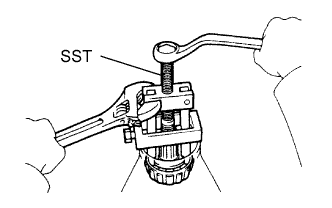 |
Using SST, remove the front tapered roller bearing from the drive pinion.
| 18. INSTALL REAR DIFFERENTIAL DRIVE PINION BEARING SPACER |
Install a new bearing spacer.
| 19. INSTALL REAR DRIVE PINION FRONT TAPERED ROLLER BEARING |
|
Install the rear drive pinion front tapered roller bearing to the drive pinion.
| 20. INSTALL REAR DIFFERENTIAL DRIVE PINION OIL SLINGER |
|
Install the oil slinger, as shown in the illustration.
| 21. INSTALL REAR DIFFERENTIAL CARRIER OIL SEAL |
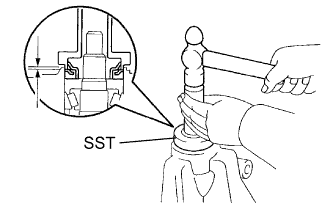 |
Using SST and a hammer, install a new oil seal.
Apply MP grease to the oil seal lip.
| 22. INSTALL REAR DIFFERENTIAL DUST DEFLECTOR |
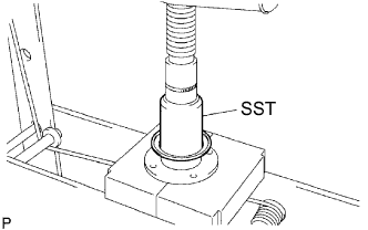 |
Using SST and a press, install a new dust deflector.
| 23. INSTALL REAR DRIVE PINION COMPANION FLANGE SUB-ASSEMBLY |
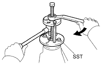 |
Using SST, install the companion flange to the drive pinion.
Coat the threads of a new nut with hypoid gear oil LSD.
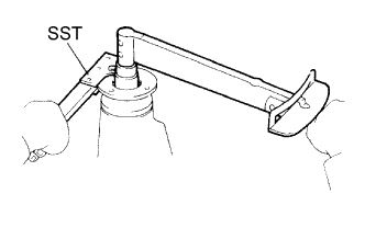 |
Using SST to hold the flange, torque the nut.
| 24. INSPECT DIFFERENTIAL DRIVE PINION PRELOAD |
|
Using a torque wrench, measure the preload of the drive pinon.
| 25. INSPECT TOTAL PRELOAD |
|
Using a torque wrench, measure the preload.
| 26. INSPECT DIFFERENTIAL RING GEAR BACKLASH |
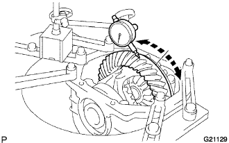 |
Using a dial gauge, check the backlash of the ring gear.
| 27. INSPECT REAR DRIVE PINION COMPANION FLANGE SUB-ASSEMBLY |
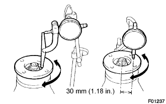 |
Using a dial gauge, measure the runout of the companion flange vertically.
| 28. INSTALL REAR DRIVE PINION NUT |
Using a chisel and hammer, stake the drive pinion nut.
| 29. INSTALL REAR DIFFERENTIAL SIDE GEAR SHAFT SEAL OIL |
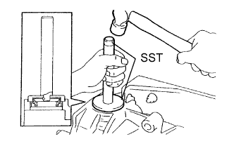 |
Using SST and a hammer, install 2 new oil seals.
Apply MP grease to the oil seal lip.
| 30. INSTALL REAR DIFFERENTIAL SIDE GEAR SHAFT DUST COVER |
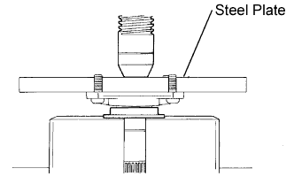 |
Using a steel plate and a press, install a new dust cover.
| 31. INSTALL REAR DIFFERENTIAL SIDE GEAR SHAFT SUB-ASSEMBLY |
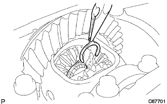 |
Install the 2 side gear shaft to the differential case.
Using needle nose pliers, install 2 new snap rings to the 2 side gear shafts.
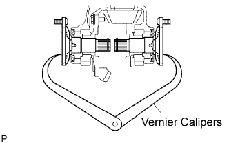 |
Using vernier calipers, measure the distance between the right and left side gear shafts, as shown in the illustration.
| 32. INSTALL REAR DIFFERENTIAL CARRIER COVER |
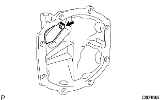 |
Install the oil deflector and bolt to the carrier cover.
Install the breather plug to the carrier cover.
Clean contacting surfaces of any residual FIPG material using gasoline or alcohol.
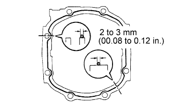 |
Apply FIPG to the carrier.
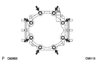 |
Install the carrier cover with the 8 bolts.