SLIDE DOOR CLOSER SYSTEM > TERMINALS OF ECU |
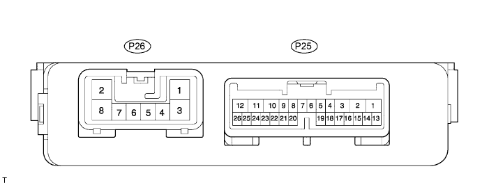
| CHECK POWER SLIDE DOOR ECU LH (WITH POWER SLIDE DOOR) |
Disconnect the P25 and P26 ECU connectors, and check the voltage and resistance of each terminal of the wire harness side connectors.
| Terminal No. | Wiring Color | Condition | Specified Condition |
| P26-2 (B) - Body ground | B-W - Body ground | Constant | 10 to 14 V |
| P25-10 (ECUB) - Body ground | W - Body ground | Constant | 10 to 14 V |
| P26-8 (GND) - Body ground | W-B - Body ground | Constant | Below 1 Ω |
| P25-3 (HSW) - Body ground | W-R - Body ground | Rear door inside / outside handle NOT PULLED → PULLED | 10 kΩ or higher → Below 1 Ω |
| P25-7 (HAF) - Body ground | GR-B - Body ground | Slide door OPEN → CLOSED | Below 1 Ω → 10 kΩ or higher |
| P25-8 (FUL) - Body ground | Y-R - Body ground | Slide door OPEN → CLOSED | Below 1 Ω → 10 kΩ or higher |
| P25-20 (POL) - Body ground | L-W - Body ground | NOT COMPLETELY CLOSED | 10 kΩ or higher |
| Slide door OPEN → CLOSED | 10 kΩ or higher → 10 kΩ or higher after momentarily being 1 Ω | ||
| P25-21 (POS) - Body ground | BR-W - Body ground | Slide door OPEN → Closer in operation → CLOSED | 10 kΩ or higher → Below 1 Ω → 10 kΩ or higher |
Reconnect the ECU connectors, and check the voltage of each terminal of the connectors.
| Terminal No. | Wiring Color | Condition | Specified Condition |
| P25-12 (DC+) - Body ground | R - Body ground | Slide door OPEN → NOT COMPLETELY CLOSED → Motor in normal rotation (Right turn) → Motor in reverse rotation (Left turn) → Operation completed (Back door CLOSED) | Below 1 V → Below 1 V → 10 to 14 V → Below 1 V → Below 1 V |
| P25-11 (DC-) - Body ground | W - Body ground | Slide door OPEN → NOT COMPLETELY CLOSED → Motor in normal rotation (Right turn) → Motor in reverse rotation (Left turn) → Operation completed (Back door CLOSED) | Below 1 V → Below 1 V → Below 1 V → 10 to 14 V → Below 1 V |
| CHECK POWER SLIDE DOOR ECU RH |
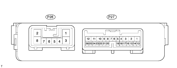
Disconnect the P27 and P28 ECU connectors, and check the voltage and resistance of each terminal of the wire harness side connectors.
| Terminal No. | Wiring Color | Condition | Specified Condition |
| P28-2 (B) - Body ground | B - Body ground | Constant | 10 to 14 V |
| P27-10 (ECUB) - Body ground | W - Body ground | Constant | 10 to 14 V |
| P28-8 (GND) - Body ground | W-B - Body ground | Constant | Below 1 Ω |
| P27-3 (HSW) - Body ground | W-R - Body ground | Rear door inside / outside handle NOT PULLED → PULLED | 10 kΩ or higher → Below 1 Ω |
| P27-7 (HAF) - Body ground | GR-B - Body ground | Slide door OPEN → CLOSED | Below 1 Ω → 10 kΩ or higher |
| P27-8 (FUL) - Body ground | Y-R - Body ground | Slide door OPEN → CLOSED | Below 1 Ω → 10 kΩ or higher |
| P27-20 (POL) - Body ground | L-W - Body ground | NOT COMPLETELY CLOSED | 10 kΩ or higher |
| Slide door OPEN → CLOSED | 10 kΩ or higher → 10 kΩ or higher after momentarily being 1 Ω | ||
| P27-21 (POS) - Body ground | BR-W - Body ground | Slide door OPEN → Closer in operation → CLOSED | 10 kΩ or higher → Below 1 Ω → 10 kΩ or higher |
Reconnect the ECU connectors, and check the voltage of each terminal of the connectors.
| Terminal No. | Wiring Color | Condition | Specified Condition |
| P27-12 (DC+) - Body ground | R - Body ground | Slide door OPEN → NOT COMPLETELY CLOSED → Motor in normal rotation (Right turn) → Motor in reverse rotation (Left turn) → Operation completed (Back door CLOSED) | Below 1 V → Below 1 V → 10 to 14 V → Below 1 V → Below 1 V |
| P27-11 (DC-) - Body ground | W - Body ground | Slide door OPEN → NOT COMPLETELY CLOSED → Motor in normal rotation (Right turn) → Motor in reverse rotation (Left turn) → Operation completed (Back door CLOSED) | Below 1 V → Below 1 V → Below 1 V → 10 to 14 V → Below 1 V |
| CHECK SLIDE DOOR CLOSER RELAY LH (WITHOUT POWER SLIDE DOOR) |

Disconnect the S37 relay connector, and check the voltage and resistance of each terminal of the wire harness side connectors.
| Terminal No. | Wiring Color | Condition | Specified Condition |
| S37-5 (ECUB) - Body ground | B-W - Body ground | Constant | 10 to 14 V |
| S37-7 (GND) - Body ground | W-B - Body ground | Constant | Below 1 Ω |
| S37-8 (SGND) - Body ground | W-B - Body ground | Constant | Below 1 Ω |
| S37-4 (HAF) - Body ground | GR-B - Body ground | Slide door OPEN → CLOSED | Below 1 Ω → 10 kΩ or higher |
| S37-3 (FUL) - Body ground | Y-R - Body ground | Slide door OPEN → CLOSED | Below 1 Ω → 10 kΩ or higher |
| S37-9 (POL) - Body ground | L-W - Body ground | NOT COMPLETELY CLOSED | 10 kΩ or higher |
| Slide door OPEN → CLOSED | 10 kΩ or higher → 10 kΩ or higher after momentarily being 1 Ω | ||
| S37-10 (POS) - Body ground | BR-W - Body ground | Slide door OPEN → Closer in operation → CLOSED | 10 kΩ or higher → Below 1 Ω → 10 kΩ or higher |
Reconnect the relay connector, and check the voltage of each terminal of the connectors.
| Terminal No. | Wiring Color | Condition | Specified Condition |
| S37-2 (DC+) - Body ground | R - Body ground | Slide door OPEN → NOT COMPLETELY CLOSED → Motor in normal rotation (Right turn) → Motor in reverse rotation (Left turn) → Operation completed (Back door CLOSED) | Below 1 V → Below 1 V → 10 to 14 V → Below 1 V → Below 1 V |
| S37-1 (DC-) - Body ground | W - Body ground | Slide door OPEN → NOT COMPLETELY CLOSED → Motor in normal rotation (Right turn) → Motor in reverse rotation (Left turn) → Operation completed (Back door CLOSED) | Below 1 V → Below 1 V → Below 1 V → 10 to 14 V → Below 1 V |