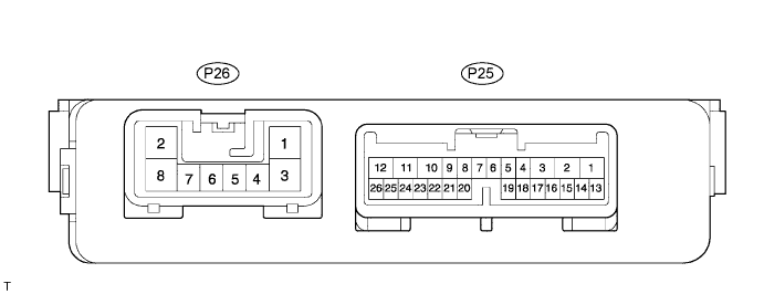
POWER SLIDE DOOR SYSTEM > TERMINALS OF ECU |
| CHECK POWER SLIDE DOOR ECU LH |
Disconnect the P25 and P26 ECU connectors, and check the voltage and resistance of each terminal of the wire harness side connectors.
| Terminal No. | Wiring Color | Condition | Specified Condition |
| P26-2 (B) - Body ground | B-W - Body ground | Constant | 10 to 14 V |
| P25-10 (ECUB) - Body ground | W - Body ground | Constant | 10 to 14 V |
| P26-8 (GND) - Body ground | W-B - Body ground | Constant | Below 1 Ω |
| P25-4 (CSW) - Body ground | L - Body ground | Power slide door control switch LH OFF → ON | 10 kΩ or higher → Below 1 Ω |
| P25-3 (HSW) - Body ground | W-R - Body ground | Rear door inside / outside handle NOT PULLED → PULLED | 10 kΩ or higher → Below 1 Ω |
| P25-18 (CPSW) - Body ground | P-B - Body ground | Child lock lever LH UNLOCK → LOCK | 10 kΩ or higher → Below 1 Ω |
| P25-17 (FLSW) - Body ground | R-W - Body ground | Fuel lid CLOSED → OPEN | 10 kΩ or higher → Below 1 Ω |
| P25-16 (OS) - P25-15 (OSG) | W-L - W-G | Power slide door touch sensor LH FREE → PRESSED | Approx. 1 kΩ → Less than 100 Ω |
| P25-22 (MPX1) - Body ground | R - Body ground | BEAN line | 10 kΩ or higher |
Reconnect the ECU connectors, and check the voltage of each terminal of the connectors.
| Terminal No. | Wiring Color | Condition | Specified Condition |
| P25-6 (MSW) - Body ground | P - Body ground | Power slide door main switch OFF → ON | 0 V → Pulse generation |
| P26-5 (RACT) - Body ground | B - Body ground | Slide door fully closed and A*1, B*2 or C*3 switch turned ON → Slide door in opening operation → Slide door fully open | 0 V → 10 to 14 V → 0 V |
| P25-2 (BZR+) - Body ground | B-R - Body ground | All conditions necessary for warning buzzer to sound*4 are met → Any condition necessary for sounding warning buzzer to stop*5 is met | 10 to 14 V (a cycle of approx. 0.3 sec.) → 0 V |
| P25-1 (BZR-) - Body ground | R-Y - Body ground | ||
| P25-13 (SEL*6) - Body ground | W-B - Body ground | Constant | 0 V |
| P25-26 (DSV) - P25-23 (DSG) | W-G - Y-B | Constant | 10 to 14 V |
| P25-25 (DS1) - P25-23 (DSG) | R-G - Y-B | Slide door fully closed and A, B or C switch turned ON → Slide door in opening operation → Slide door fully open | 0 V → Alternating between 10 to 14 V and 0 V→ 0 V |
| P25-24 (DS2) - P25-23 (DSG) | G-W - Y-B | ||
| P26-7 (CL+) - Body ground | V-W - Body ground | Slide door fully open and A, B or C switch turned ON → Slide door in closing operation → Slide door fully closed | 0 V → 10 to 14 V → 0 V |
| P26-6 (CL-) - Body ground | B-Y - Body ground | Slide door fully closed and A, B or C switch turned ON → Slide door in opening operation → Slide door fully open | 0 V → 10 to 14 V → 0 V |
| P26-1 (SD+) - Body ground | G - Body ground | Slide door fully closed and A, B or C switch turned ON → Slide door in opening operation → Slowdown point → Slide door fully open | 0 V → 10 to 14 V → Alternating between 10 to 14 V and 0 V→ 0 V |
| P26-3 (SD-) - Body ground | Y - Body ground | Slide door fully open and A, B or C switch turned ON → Slide door in closing operation → Slowdown point → Slide door fully closed | 0 V → 10 to 14 V → Alternating between 10 to 14 V and 0 V→ 0 V |
| CHECK POWER SLIDE DOOR ECU RH |
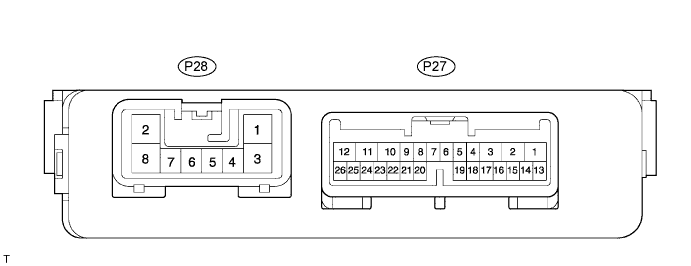
Disconnect the P27 and P28 ECU connectors, and check the voltage or resistance of each terminal of the wire harness side connectors.
| Terminal No. | Wiring Color | Condition | Specified Condition |
| P28-2 (B) - Body ground | B - Body ground | Constant | 10 to 14 V |
| P27-10 (ECUB) - Body ground | W - Body ground | Constant | 10 to 14 V |
| P28-8 (GND) - Body ground | W-B - Body ground | Constant | Below 1 Ω |
| P27-4 (CSW) - Body ground | L - Body ground | Power slide door control switch RH OFF → ON | 10 kΩ or higher → Below 1 Ω |
| P27-3 (HSW) - Body ground | W-R - Body ground | Rear door inside / outside handle NOT PULLED → PULLED | 10 kΩ or higher → Below 1 Ω |
| P27-18 (CPSW) - Body ground | P-B - Body ground | Child lock lever RH UNLOCK → LOCK | 10 kΩ or higher → Below 1 Ω |
| P27-16 (OS) - P27-15 (OSG) | W-L - W-G | Power slide door touch sensor RH FREE → PRESSED | Approx. 1 kΩ → Less than 100 Ω |
| P27-22 (MPX1) - Body ground | R - Body ground | BEAN line | 10 kΩ or higher |
Reconnect the ECU connectors, and check the voltage of each terminal of the connectors.
| Terminal No. | Wiring Color | Condition | Specified Condition |
| P27-6 (MSW) - Body ground | P - Body ground | Power slide door main switch OFF → ON | 0 V → Pulse generation |
| P27-5 (MSE) - Body ground | R-W - Body ground | ||
| P28-5 (RACT) - Body ground | B - Body ground | Slide door fully closed and A*1, B*2 or C*3 switch turned ON → Slide door in opening operation → Slide door fully open | 0 V → 10 to 14 V → 0 V |
| P27-2 (BZR+) - Body ground | B-R - Body ground | All conditions necessary for warning buzzer to sound*4 are met → Any condition necessary for sounding warning buzzer to stop*5 is met | 10 to 14 V (a cycle of approx. 0.3 sec.) → 0 V |
| P27-1 (BZR-) - Body ground | R-Y - Body ground | ||
| P27-26 (DSV) - P27-23 (DSG) | W-G - Y-B | Constant | 10 to 14 V |
| P27-25 (DS1) - P27-23 (DSG) | R-G - Y-B | Slide door fully closed and A, B or C switch turned ON → Slide door in opening operation → Slide door fully open | 0 V → Alternating between 10 to 14 V and 0 V→ 0 V |
| P27-24 (DS2) - P27-23 (DSG) | G-W - Y-B | ||
| P28-7 (CL+) - Body ground | V-W - Body ground | Slide door fully open and A, B or C switch turned ON → Slide door in closing operation → Slide door fully closed | 0 V → 10 to 14 V → 0 V |
| P28-6 (CL-) - Body ground | B-Y - Body ground | Slide door fully closed and A, B or C switch turned ON → Slide door in opening operation → Slide door fully open | 0 V → 10 to 14 V → 0 V |
| P28-1 (SD+) - Body ground | G - Body ground | Slide door fully closed and A, B or C switch turned ON → Slide door in opening operation → Slowdown point → Slide door fully open | 0 V → 10 to 14 V → Alternating between 10 to 14 V and 0 V→ 0 V |
| P28-3 (SD-) - Body ground | Y - Body ground | Slide door fully open and A, B or C switch turned ON → Slide door in closing operation → Slowdown point → Slide door fully closed | 0 V → 10 to 14 V → Alternating between 10 to 14 V and 0 V→ 0 V |