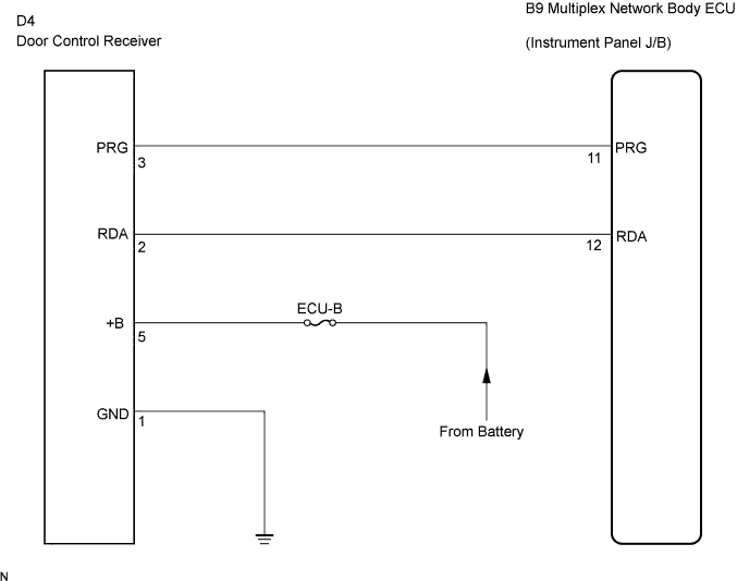
DTC B1242 Wireless Door Lock Tuner Circuit Malfunction |
| DTC No. | DTC Detection Condition | Suspected Area |
| B1242 | Within 1 second after PRG signal is output from multiplex network body ECU during self-diagnostic mode, corresponding RDA signal is not input |
|
| 1.CHECK HARNESS AND CONNECTOR (DOOR CONTROL RECEIVER - MULTIPLEX NETWORK BODY ECU) |
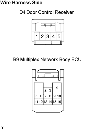 |
Disconnect the D4 receiver connector.
Disconnect the B9 ECU connector.
Check the resistance between the wire harness side connectors.
| Symbol (Terminal No. ) | Specified Condition |
| RDA (D4-2) - RDA (B9-12) | Below 1 Ω |
| PRG (D4-3) - PRG (B9-11) | Below 1 Ω |
Check the voltage and resistance between the D4 receiver connector or B9 ECU connector and the body ground.
| Symbol (Terminal No. ) | Specified Condition |
| +B (D4-5) - Body ground | 10 to 14 V |
| GND (D4-1) - Body ground | Below 1 Ω |
| RDA (D4-2) or RDA (B9-12) - Body ground | 10 kΩ or higher |
| PRG (D4-3) or PRG (B9-11) - Body ground | 10 kΩ or higher |
|
| ||||
| OK | |
 |
| 2.CHECK DOOR CONTROL RECEIVER |
Check that the DTC is not output.
|
| ||||
| NG | ||
 | ||
| ||
