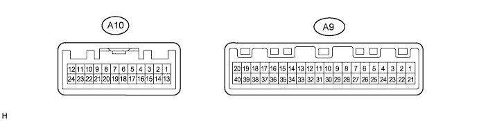
AIR CONDITIONING SYSTEM (for Manual Air Conditioning System) > TERMINALS OF ECU |
| A/C AMPLIFIER |
| Terminal No. (Symbols) | Wiring Color | Description | Condition | Specified Condition |
| A9-1 (S5) - A9-26 (SG) | BR-R - LG-R | Power supply for air mix control damper position sensor | Ignition switch: ON | 4.5 to 5.5 V |
| A9-3 (TE) - A9-7 (SG-4) | G-B - Y | A/C evaporator temperature sensor signal | Ignition switch: ON Evaporator temperature: 0°C (32°F) | 2.0 to 2.4 V |
| A9-3 (TE) - A9-7 (SG-4) | G-B - Y | A/C evaporator temperature sensor signal | Ignition switch: ON Evaporator temperature: 15°C (59°F) | 1.4 to 1.8 V |
| A9-4 (MPX+) - Body ground | V - Body ground | Multiplex communication system | Multiplex communication circuit | Pulse generation |
| A9-5 (MPX-) - Body ground | R-L - Body ground | Multiplex communication system | Multiplex communication circuit | Pulse generation |
| A9-6 (GND) - Body ground | W-B - Body ground | Ground for main power supply | Always | Below 1 V |
| A9-7 (SG-4) - Body ground | Y - Body ground | Ground for A/C evaporator temperature sensor | Always | Below 1 V |
| A9-8 (FTIN) - A9-6 (GND) | B-O - W-B | Mode control switch operation signal | Ignition switch: ON Rear mode control switch (FOOT): OFF | 4.5 to 5.5 V |
| A9-8 (FTIN) - A9-6 (GND) | B-O - W-B | Mode control switch operation signal | Ignition switch: ON Rear mode control switch (FOOT): ON | Below 1 V |
| A9-9 (BLIN) - A9-6 (GND) | W - W-B | Mode control switch operation signal | Ignition switch: ON Rear mode control switch (B/L): OFF | 4.5 to 5.5 V |
| A9-9 (BLIN) - A9-6 (GND) | W - W-B | Mode control switch operation signal | Ignition switch: ON Rear mode control switch (B/L): ON | Below 1 V |
| A9-10 (FCIN) - A9-6 (GND) | BR-B - W-B | Mode control switch operation signal | Ignition switch: ON Rear mode control switch (FACE): OFF | 4.5 to 5.5 V |
| A9-10 (FCIN) - A9-6 (GND) | BR-B - W-B | Mode control switch operation signal | Ignition switch: ON Rear mode control switch (FACE): ON | Below 1 V |
| A9-11 (RDSW) - A9-6 (GND) | Y-G - W-B | Rear defogger operation signal | Ignition switch: ON REAR DEF switch: OFF | 4.5 to 5.5 V |
| A9-11 (RDSW) - A9-6 (GND) | Y-G - W-B | Rear defogger operation signal | Ignition switch: ON REAR DEF switch: ON | Below 1 V |
| A9-12 (SOL+) - A9-6 (GND) | L - W-B | A/C compressor operation signal | Engine is runningA/C switch: ON Front blower control dial: LO | Pulse generation (See waveform 1) |
| A9-13 (AOD) - A9-6 (GND) | G-O - W-B | Air outlet control servo motor operation signal | Ignition switch: ON Front mode control dial: FOOT | Below 1 V |
| A9-13 (AOD) - A9-6 (GND) | G-O - W-B | Air outlet control servo motor operation signal | Ignition switch: ON Front mode control dial: DEF | 11 to 14 V |
| A9-14 (AOF) - A9-6 (GND) | L-O - W-B | Air outlet control servo motor operation signal | Ignition switch: ON Front mode control dial: DEF | Below 1 V |
| A9-14 (AOF) - A9-6 (GND) | L-O - W-B | Air outlet control servo motor operation signal | Ignition switch: ON Front mode control dial: FOOT | 11 to 14 V |
| A9-15 (FOOT) - A9-6 (GND) | G-Y - W-B | Rear air outlet control servo motor operation signal | Ignition switch: ON Rear mode control switch (FOOT): OFF | Below 1 V |
| A9-15 (FOOT) - A9-6 (GND) | G-Y - W-B | Rear air outlet control servo motor operation signal | Ignition switch: ON Rear mode control switch (FOOT): ON | 11 to 14 V |
| A9-16 (FACE) - A9-6 (GND) | LG-B - W-B | Rear air outlet control servo motor operation signal | Ignition switch: ON Rear mode control switch (FACE): OFF | Below 1 V |
| A9-16 (FACE) - A9-6 (GND) | LG-B - W-B | Rear air outlet control servo motor operation signal | Ignition switch: ON Rear mode control switch (FACE): ON | 11 to 14 V |
| A9-17 (+B) - A9-6 (GND) | W-L - W-B | Power source (Battery) | Always | 11 to 14 V |
| A9-18 (IG+) - A9-6 (GND) | R-Y - W-B | Power source (IG) | Ignition switch: OFF | Below 1 V |
| A9-18 (IG+) - A9-6 (GND) | R-Y - W-B | Power source (IG) | Ignition switch: ON | 11 to 14 V |
| A9-19 (MHH) - A9-6 (GND) | V-Y - W-B | Rear air mix control servo motor operation signal | Ignition switch: ON Rear temperature control dial: MAX COLD | Below 1 V |
| A9-19 (MHH) - A9-6 (GND) | V-Y - W-B | Rear air mix control servo motor operation signal | Ignition switch: ON Rear temperature control dial: MAX HOT | 11 to 14 V |
| A9-20 (MCH) - A9-6 (GND) | GR-L - W-B | Rear air mix control servo motor operation signal | Ignition switch: ON Rear temperature control dial: MAX HOT | Below 1 V |
| A9-20 (MCH) - A9-6 (GND) | GR-L - W-B | Rear air mix control servo motor operation signal | Ignition switch: ON Rear temperature control dial: MAX COLD | 11 to 14 V |
| A9-21 (S5) - A9-6 (GND) | B-W - W-B | Power supply for mode control switch | Ignition switch: ON | 4.5 to 5.5 V |
| A9-22 (S5-1) - A9-27 (SG-1) | P-L - GR-L | Power supply for air outlet control damper position sensor | Ignition switch: ON | 4.5 to 5.5 V |
| A9-23 (S5) - A9-6 (GND) | P-L - W-B | Power supply for rear air outlet control damper position sensor | Ignition switch: ON | 4.5 to 5.5 V |
| A9-24 (TSET) - A9-6 (GND) | R-G - W-B | Rear temperature control dial operation signal | Ignition switch: ON Rear temperature control dial: ON | 0 to 5 V |
| A9-25 (BSET) - A9-6 (GND) | GR-G - W-B | Rear blower control dial operation signal | Ignition switch: ON Rear blower control dial: ON | 0 to 5 V |
| A9-26 (SG) - Body ground | LG-R - Body ground | Ground for air mix control damper position sensor | Always | Below 1 V |
| A9-27 (SG-1) - Body ground | GR-L - Body ground | Ground for air outlet control damper position sensor | Always | Below 1 V |
| A9-28 (SG) - Body ground | V-W - Body ground | Ground for rear A/C control assembly | Always | Below 1 V |
| A9-29 (SG) - Body ground | W-R - Body ground | Ground for rear air outlet control damper position sensor | Always | Below 1 V |
| A9-30 (SG-6) - Body ground | W-G - Body ground | Ground for A/C lock sensor, A/C pressure sensor and A/C ambient temperature sensor | Always | Below 1 V |
| A9-35 (THOT) - A9-6 (GND) | L-B - W-B | Air mix control servo motor operation signal | Ignition switch: ON Front temperature control dial: MAX. COLD | Below 1 V |
| A9-35 (THOT) - A9-6 (GND) | L-B - W-B | Air mix control servo motor operation signal | Ignition switch: ON Front temperature control dial: MAX. HOT | 11 to 14 V |
| A9-36 (TCOL) - A9-6 (GND) | P-G - W-B | Air mix control servo motor operation signal | Ignition switch: ON Front temperature control dial: MAX. HOT | Below 1 V |
| A9-36 (TCOL) - A9-6 (GND) | P-G - W-B | Air mix control servo motor operation signal | Ignition switch: ON Front temperature control dial: MAX. COLD | 11 to 14 V |
| A9-38 (A/CB) - A9-6 (GND) | B - W-B | Power source (Battery) | Ignition switch: ON Front blower control dial: OFF | Below 1 V |
| A9-38 (A/CB) - A9-6 (GND) | B - W-B | Power source (Battery) | Ignition switch: ON Front blower control dial: ON | 11 to 14 V |
| A9-40 (ACC) - A9-6 (GND) | P - W-B | Power source (ACC) | Ignition switch: OFF | Below 1 V |
| A9-40 (ACC) - A9-6 (GND) | P - W-B | Power source (ACC) | Ignition switch: ACC | 11 to 14 V |
| A10-2 (LOCK) - A9-30 (SG-6) | W-L - W-G | A/C lock sensor signal | Engine is running Front blower control dial: LO A/C switch: ON | Pulse generation (See waveform 2) |
| A10-6 (BLWC) - A9-6 (GND) | L-W - W-B | Rear blower motor operation signal | Ignition switch: ON Rear blower control dial: ON | 1.7 to 2.0 V |
| A10-7 (VMC) - A9-6 (GND) | P-B - W-B | Rear blower motor operation signal | Ignition switch: ON Rear blower control dial: ON | 0 to 9 V |
| A10-9 (TAM) - A9-30 (SG-6) | B-R - W-G | A/C ambient temperature sensor signal | Ignition switch: ON Ambient temperature: 25°C (77°F) | 1.35 to 1.75 V |
| A10-9 (TAM) - A9-30 (SG-6) | B-R - W-G | A/C ambient temperature sensor signal | Ignition switch: ON Ambient temperature: 40°C (104°F) | 0.85 to 1.25 V |
| A10-10 (PRE) - A9-30 (SG-6) | V - W-G | A/C pressure sensor signal | Start engine Operate A/C system Refrigerant pressure: Abnormal pressure (more than 3140 kPa (32.0 kgf/cm2, 455 psi)) | 4.74 V or higher |
| A10-10 (PRE) - A9-30 (SG-6) | V - W-G | A/C pressure sensor signal | Start engine Operate A/C system Refrigerant pressure: Abnormal pressure (less than 196 kPa (2.0 kgf/cm2, 28 psi)) | Below 0.76 V |
| A10-10 (PRE) - A9-30 (SG-6) | V - W-G | A/C pressure sensor signal | Start engine Operate A/C system Refrigerant pressure: Normal pressure (less than 3140 kPa (32.0 kgf/cm2, 455 psi) and more than 196 kPa (2.0 kgf/cm2, 28 psi)) | 0.76 to 4.74 V |
| A10-11 (TPO) - A9-27 (SG-1) | LG - GR-L | Air outlet control damper position sensor signal | Ignition switch: ON Front mode control dial: FOOT→DEF | 1.0 to 4.0 V |
| A10-12 (TP) - A9-26 (SG) | L-R - LG-R | Air mix control damper position sensor signal | Ignition switch: ON Front temperature control dial: MAX. HOT → MAX. COLD | 1.0 to 4.0 V |
| A10-19 (REC) - A9-6 (GND) | GR-R - W-B | Air inlet control servo motor operation signal | Ignition switch: ON R/F switch: FRESH | Below 1 V |
| A10-19 (REC) - A9-6 (GND) | GR-R - W-B | Air inlet control servo motor operation signal | Ignition switch: ON R/F switch: RECIRCULATION | 11 to 14 V |
| A10-20 (FRS) - A9-6 (GND) | W-L - W-B | Air inlet control servo motor operation signal | Ignition switch: ON R/F switch: RECIRCULATION | Below 1 V |
| A10-20 (FRS) - A9-6 (GND) | W-L - W-B | Air inlet control servo motor operation signal | Ignition switch: ON R/F switch: FRESH | 11 to 14 V |
| A10-21 (HRC) - A9-6 (GND) | R-G - W-B | Rear blower motor operation signal | Ignition switch: ON Rear blower control dial: OFF | 11 to 14 V |
| A10-21 (HRC) - A9-6 (GND) | R-G - W-B | Rear blower motor operation signal | Ignition switch: ON Rear blower control dial: ON | Below 1 V |
| A10-22 (MGC) - A9-6 (GND) | R-L - W-B | A/C compressor magnetic clutch relay operation signal | Ignition switch: ON A/C switch: OFF | 11 to 14 V |
| A10-22 (MGC) - A9-6 (GND) | R-L - W-B | A/C compressor magnetic clutch relay operation signal | Ignition switch: ON A/C switch: ON | Below 1 V |
| A10-23 (TPH) - A9-29 (SG) | B - W-R | Rear air mix control damper position sensor signal | Ignition switch: ON Rear temperature control dial: MAX. HOT → MAX. COLD | 1.0 to 4.0 V |
| A10-24 (TPM) - A9-29 (SG) | G - W-R | Rear air outlet control damper position sensor signal | Ignition switch: ON Rear mode control switch: FOOT → FACE | 1.0 to 4.0 V |
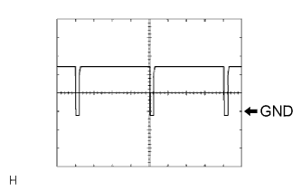 |
Waveform 1:
| Item | Contents |
| Terminal No. (Symbols) | A9-12 (SOL+) - A9-6 (GND) |
| Tool Setting | 5 V/DIV., 500 μs/DIV. |
| Vehicle Condition | Engine is running A/C switch: ON Front blower control dial: LO |
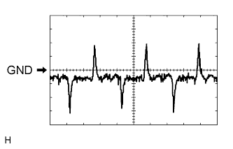 |
Waveform 2:
| Item | Contents |
| Terminal No. (Symbols) | A10-2 (LOCK) - A9-30 (SG-6) |
| Tool Setting | 200 mV/DIV., 10 ms/DIV. |
| Vehicle Condition | Engine is running A/C switch: ON Front blower control dial: LO |