 |
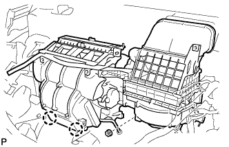
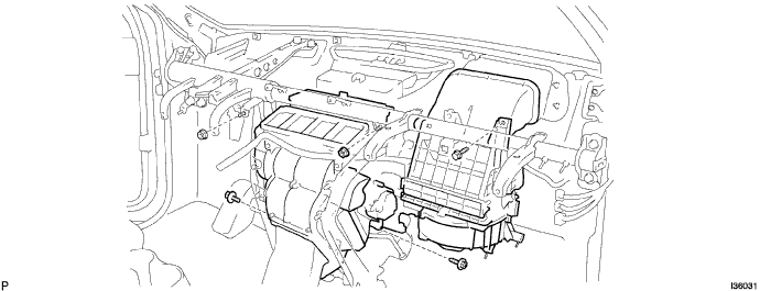
Engage the 2 claws.
AIR CONDITIONING UNIT > INSTALLATION |
| 1. TEMPORARILY TIGHTEN AIR CONDITIONING UNIT ASSEMBLY |
|
Engage the 2 claws.
Temporarily tighten the air conditioning unit assembly with the nut.
| 2. INSTALL LOWER DEFROSTER NOZZLE ASSEMBLY |
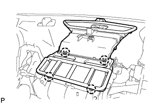 |
Engage the 4 claws and install the lower defroster nozzle assembly.
| 3. INSTALL INSTRUMENT PANEL REINFORCEMENT |
Install the instrument panel reinforcement with the 10 bolts.
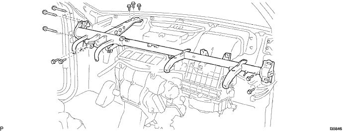
Install the 13 clamps.
Connect the connectors.
Install the screw.
Install the 6 nuts.
| 4. INSTALL AIR CONDITIONING UNIT ASSEMBLY |
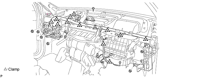
Install the air conditioner unit assembly with the 3 bolts and 2 nuts.
| 5. INSTALL FRONT FENDER GARNISH RH |
| 6. INSTALL ECM |
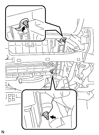 |
Install the ECM with the 2 nuts.
Connect the 5 ECM connectors.
| 7. INSTALL STEREO COMPONENT AMPLIFIER ASSEMBLY (w/ Stereo Component Amplifier) |
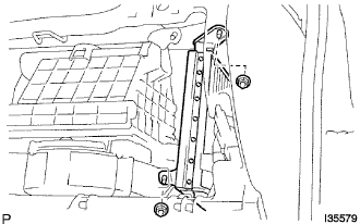 |
Install the stereo component amplifier assembly with the 2 nuts.
Connect the connectors.
| 8. INSTALL NO. 2 INSTRUMENT PANEL BRACE SUB-ASSEMBLY |
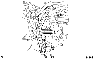 |
Install the No. 2 instrument panel brace sub-assembly with the 3 bolts and 2 nuts.
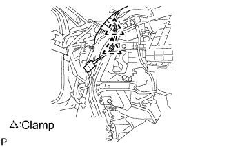 |
Engage the 2 clamps.
Connect the connector.
| 9. INSTALL NO. 1 INSTRUMENT PANEL BRACE SUB-ASSEMBLY |
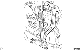 |
Install the No. 1 instrument panel brace sub-assembly with the 3 bolts and 2 nuts.
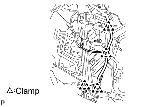 |
Engage the 4 clamps.
Install the bolt.
Connect the connector.
| 10. INSTALL NO. 5 INSTRUMENT PANEL BRACKET |
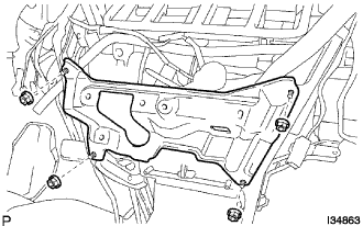 |
Install the No. 5 instrument panel bracket with the 4 nuts.
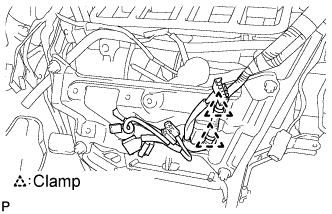 |
Engage the 2 clamps.
Connect the connector.
| 11. INSTALL SHIFT LEVER ASSEMBLY |
| 19. INSTALL HEATER WATER INLET HOSE A |
| 20. CONNECT HEATER WATER OUTLET HOSE A (FROM HEATER UNIT) |
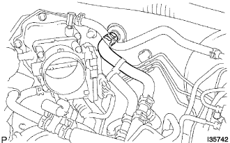 |
Using pliers, grip the claws of the clip and slide the clip to connect the heater water outlet hose A (from heater unit).
| 21. INSTALL AIR CLEANER CAP SUB-ASSEMBLY |
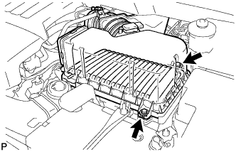 |
Install the air cleaner filter element, and air cleaner cap sub-assembly with the 2 bolts.
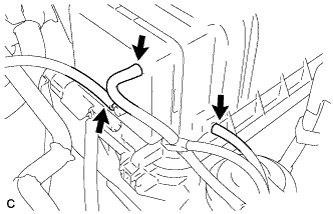 |
Connect the 3 vacuum hoses.
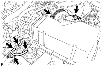 |
Tighten the bolt, connect the 2 connectors, and install the 2 vacuum hoses.
| 22. INSTALL SUCTION HOSE SUB-ASSEMBLY |
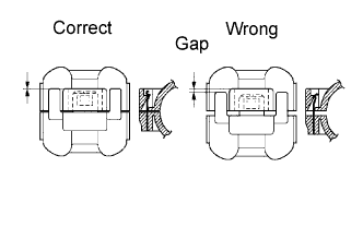 |
Lubricate a new O-ring with compressor oil and install it on the hose.
Install the suction hose sub-assembly and the piping clamp.
| 23. INSTALL COOLER REFRIGERANT LIQUID PIPE E |
Lubricate a new O-ring with compressor oil and install it to the pipe.
Install the cooler refrigerant liquid pipe E and the piping clamp.
| 24. INSTALL FRONT COWL TOP OUTER PANEL SUB-ASSEMBLY |
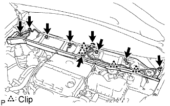 |
Install the cowl top brace and cowl top panel sub-assembly outer front with the 9 bolts.
Connect the wire harness to the cowl top panel sub-assembly outer front.
| 25. INSTALL WINDSHIELD WIPER MOTOR AND LINK ASSEMBLY |
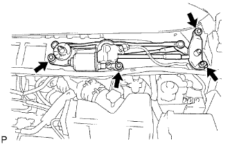 |
Install the wiper motor & link assembly with the 4 bolts.
Connect the connector.
| 26. INSTALL COWL TOP VENTILATOR LOUVER SUB-ASSEMBLY |
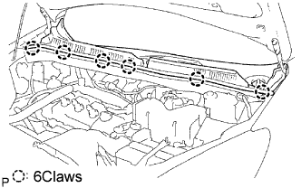 |
Install the 6 claws and the cowl top ventilator louver sub-assembly.
| 27. INSTALL FRONT WIPER ARM LH |
Operate the wiper, and stop the windshield wiper motor assembly to the automatic stop position.
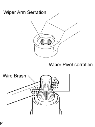 |
Scrape off the serration part of the wiper arm with a round file or equivalent.
Clean the wiper pivot serration with a wire brush.
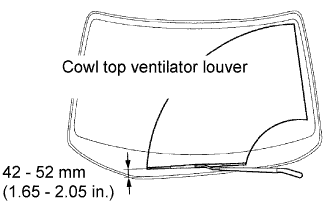 |
Install the front wiper arm LH with the nut to the position shown in the illustration.
| 28. INSTALL FRONT WIPER ARM RH |
Scrape off the serration part of the wiper arm with a round file or equivalent.
Clean the wiper pivot serration with a wire brush.
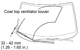 |
Install the front wiper arm RH with the nut to the position shown in the illustration.
Operate the wiper while running the water or the washer fluid over the window, and check the wiping condition and that the front wiper does not hit against the vehicle body.
| 29. INSTALL FRONT WIPER ARM HEAD CAP |
Install the 2 caps.
| 30. ADJUST SHIFT LEVER POSITION |
| 31. INSPECT SHIFT LEVER POSITION |
| 32. INSPECT KEY INTERLOCK OPERATION |
| 33. INSPECT SHIFT LOCK OPERATION |
| 34. INSPECT SHIFT LOCK RELEASE BUTTON OPERATION |
| 35. ADD ENGINE COOLANT |
Tighten the radiator drain cock plug by hand.
Tighten the 2 cylinder block drain cock plugs.
Remove the air drain cock plug from the water inlet housing.
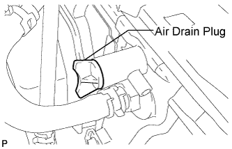 |
Loosen the air drain plug at the top of the radiator 3 or 4 turns.
Add TOYOTA Super Long Life Coolant (SLLC) to the radiator inlet opening until coolant overflows from the engine air drain cock hole. Then install the air drain cock plug to the water inlet housing.
Continue to add TOYOTA Super Long Life Coolant (SLLC) to the radiator inlet opening until coolant overflows from the radiator air drain hole. Then close the air drain plug at the top of the radiator.
Slowly fill the radiator with TOYOTA Super Long Life Coolant (SLLC).
Slowly pour coolant into the radiator reservoir tank until it reaches the FULL line.
Squeeze the No. 1 and No. 2 radiator hoses several times by hand, and then check the level of the coolant.
If the coolant level is low, add coolant.
Bleed air from the cooling system.
Warm up the engine until the thermostat opens. While the thermostat is open, circulate the coolant for several minutes.
Maintain the engine speed at 2500 to 3000 rpm.
Squeeze the inlet and outlet radiator hoses several times by hand to bleed air.
Stop the engine and wait until the engine coolant cools down.
Add engine coolant to the FULL line on the radiator reservoir.
| 36. CHARGE WITH REFRIGERANT |
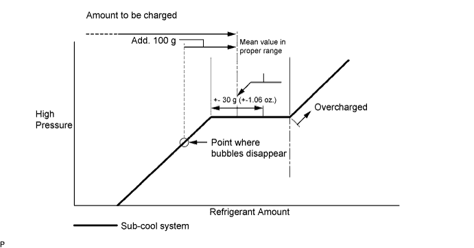
Using a vacuum pump, perform a vacuum purging.
Charge refrigerant, HFC-134a (R134a).
| 37. WARM UP ENGINE |
| 38. INSPECT FOR ENGINE COOLANT LEAK |
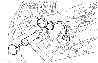 |
Fill the radiator with coolant and attach a radiator cap tester.
Warm up the engine.
Using a radiator cap tester, increase the pressure inside the radiator to 118 kPa (1.2 kgf/cm2, 17 psi), and check that the pressure does not drop.
If the pressure drops, check the hoses, radiator and water pump for leaks. If no external leaks are found, check the heater core, cylinder block and cylinder head.
| 39. INSPECT FOR REFRIGERANT LEAK |
Using a gas leak detector, check for leakage of the refrigerant.