 |
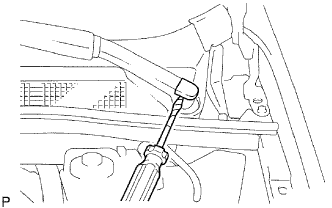
Using a small screwdriver, remove the 2 front wiper arm covers.
- HINT:
- Tape up the screwdriver tip before use.
AIR CONDITIONING UNIT > REMOVAL |
| 1. RECOVER REFRIGERANT FROM REFRIGERATION SYSTEM |
Turn the A/C switch to ON.
Operating the cooler compressor at the engine rpm of approx. 1,000 for 5 to 6 minutes, circulate the refrigerant and collect the compressor oil remaining in each component into the cooler compressor as much as possible.
Stop the engine.
Recover the refrigerant from the A/C system using a refrigerant recovery unit.
| 2. REMOVE FRONT WIPER ARM HEAD CAP |
|
Using a small screwdriver, remove the 2 front wiper arm covers.
| 3. REMOVE FRONT WIPER ARM RH |
Operate the wiper, and stop the windshield wiper motor assembly to the automatic stop position.
Remove the nut and the FR wiper arm RH.
| 4. REMOVE FRONT WIPER ARM LH |
Remove the nut and the FR wiper arm LH.
| 5. REMOVE COWL TOP VENTILATOR LOUVER SUB-ASSEMBLY |
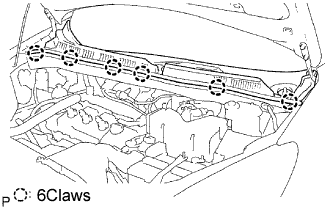 |
Remove the 6 claws and the cowl top ventilator louver sub-assembly.
| 6. REMOVE WINDSHIELD WIPER MOTOR AND LINK ASSEMBLY |
Disconnect the connector.
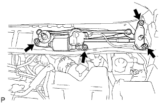 |
Remove the 4 bolts and wiper motor & link assembly.
| 7. REMOVE FRONT COWL TOP OUTER PANEL SUB-ASSEMBLY |
Disconnect the wire harness from the cowl top panel sub-assembly outer front.
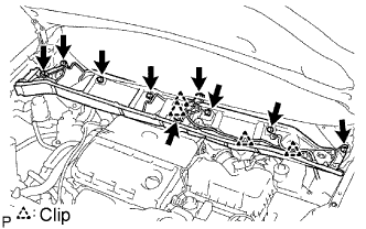 |
Remove the 9 bolts, cowl top brace and cowl top panel sub-assembly outer front.
| 8. DISCONNECT COOLER REFRIGERANT LIQUID PIPE E |
Install SST on the piping clamp.
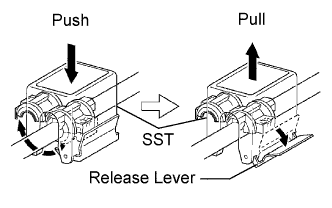 |
Push down SST and release the clamp lock.
Pull SST slightly, push the release lever, and then remove the piping clamp with SST.
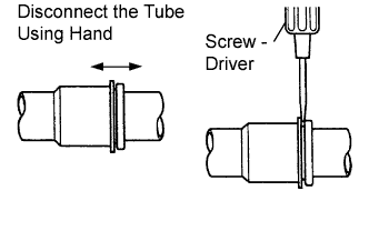 |
Disconnect the cooler refrigerant liquid pipe (to cooler unit).
| 9. DISCONNECT SUCTION HOSE SUB-ASSEMBLY |
| 10. REMOVE AIR CLEANER CAP SUB-ASSEMBLY |
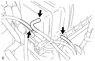 |
Disconnect the 3 vacuum hoses.
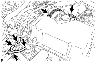 |
Loosen the bolt, disconnect the 2 connectors, and remove the 2 vacuum hoses.
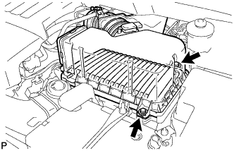 |
Remove the 2 bolts, air cleaner cap sub-assembly, and air cleaner filter element.
| 11. DISCONNECT HEATER WATER OUTLET HOSE A (FROM HEATER UNIT) |
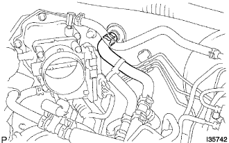 |
Using pliers, grip the claws of the clip and slide the clip to disconnect the heater water outlet hose A (from heater unit).
| 12. REMOVE HEATER WATER INLET HOSE A |
| 13. REMOVE INSTRUMENT PANEL SUB-ASSEMBLY WITH PASSENGER AIRBAG ASSEMBLY |
| 14. REMOVE SPIRAL CABLE |
Disconnect the connectors from the spiral cable.
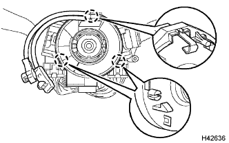 |
Disengage the 3 claws and remove the spiral cable.
| 15. REMOVE NO. 3 HEATER TO FOOT DUCT |
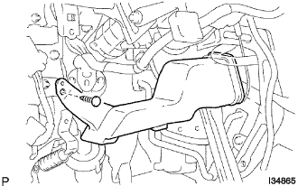 |
Remove the clip and the No. 3 heater to foot duct.
| 16. REMOVE NO. 1 HEATER TO FOOT DUCT |
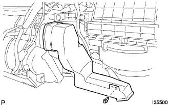 |
Remove the clip and the No. 1 heater to foot duct.
| 17. DISCONNECT TRANSMISSION CONTROL CABLE ASSEMBLY |
| 18. REMOVE SHIFT LEVER ASSEMBLY |
| 19. REMOVE NO. 5 INSTRUMENT PANEL BRACKET |
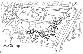 |
Release the 2 clamps and disconnect the connector.
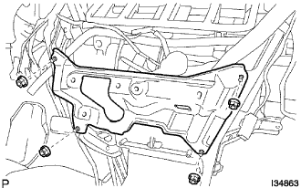 |
Remove the 4 nuts and the No. 5 instrument panel bracket.
| 20. REMOVE NO. 1 INSTRUMENT PANEL BRACE SUB-ASSEMBLY |
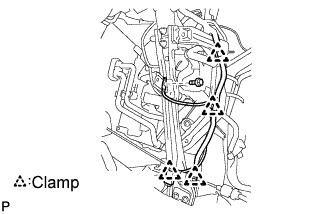 |
Release the 4 clamps and remove the bolt.
Disconnect the connector.
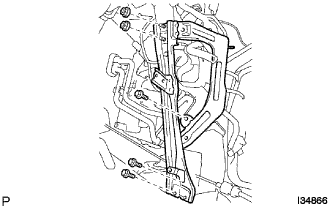 |
Remove the 3 bolts, the 2 nuts and the No. 1 instrument panel brace sub-assembly.
| 21. REMOVE NO. 2 INSTRUMENT PANEL BRACE SUB-ASSEMBLY |
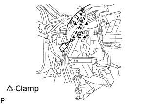 |
Release the 2 clamps and disconnect the connector.
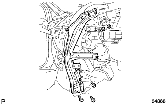 |
Remove the 3 bolts, the 2 nuts and the No. 2 instrument panel brace sub-assembly.
| 22. SEPARATE STEERING INTERMEDIATE SHAFT ASSEMBLY |
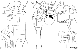 |
Loosen the bolt.
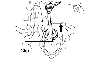 |
Release the 3 clips and separate the dust cover.
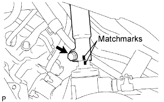 |
Align the matchmarks on the steering intermediate shaft assembly and steering gear assembly.
Remove the bolt and separate the steering intermediate shaft assembly.
| 23. REMOVE STEERING COLUMN ASSEMBLY |
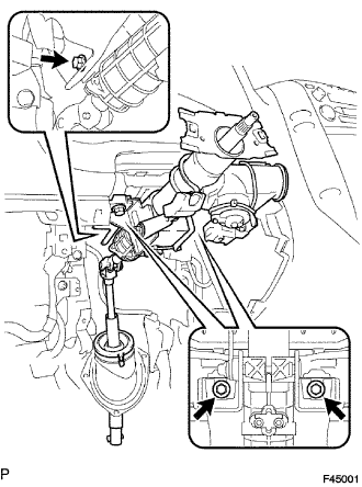 |
Disconnect the connectors and wire harness clamps.
Remove the 3 bolts and steering column assembly from the instrument panel reinforcement assembly.
| 24. REMOVE STEREO COMPONENT AMPLIFIER ASSEMBLY (w/ Stereo Component Amplifier) |
Disconnect the connectors.
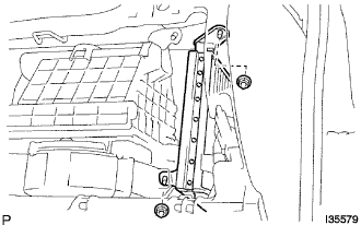 |
Remove the 2 nuts and the stereo component amplifier assembly.
| 25. REMOVE ECM |
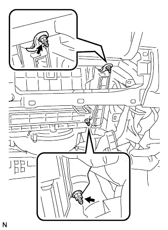 |
Disconnect the 5 ECM connectors.
Remove the 2 nuts and ECM.
| 26. REMOVE FRONT FENDER GARNISH RH |
| 27. REMOVE INSTRUMENT PANEL REINFORCEMENT |
Remove the 6 nuts.
Release the 13 clamps.
Remove the screw.
Disconnect the connectors.
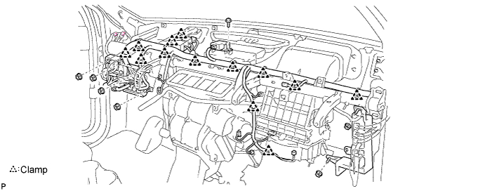
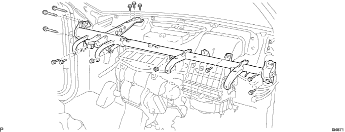
Remove the 11 bolts, 2 nuts and the instrument panel reinforcement.
| 28. REMOVE LOWER DEFROSTER NOZZLE ASSEMBLY |
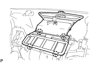 |
Release the 4 claw fittings and remove the lower defroster nozzle assembly.
| 29. REMOVE AIR CONDITIONING UNIT ASSEMBLY |
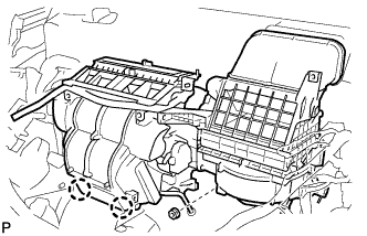 |
Release the 2 claw fittings and remove the nut and the air conditioning unit assembly.