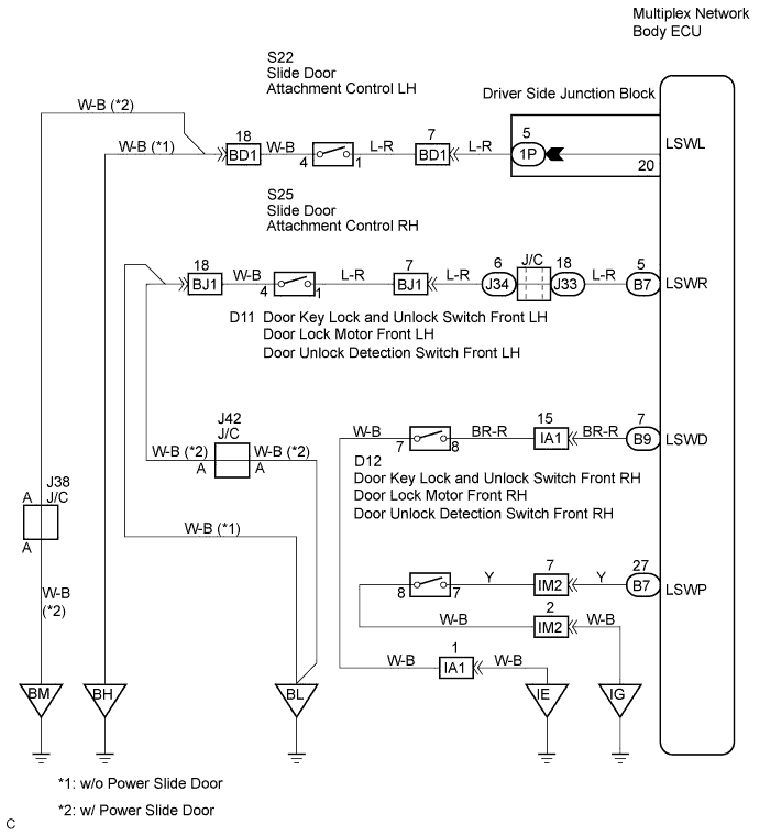
LIGHTING SYSTEM > Door LOCK Position Circuit |
| 1.READ VALUE USING TECHSTREAM |
Connect the Techstream to the DLC3.
Turn the ignition switch to ON.
Turn the Techstream on.
Enter the following menus: Body Electrical / Body / Active Test.
Read the display on the Techstream.
| Tester Display | Measurement Item/Range | Normal Condition | Diagnostic Note |
| D-Door Lock Pos SW | Driver side door lock position switch signal / ON or OFF | ON: Driver side door unlocked OFF: Driver side door locked | - |
| Passenger Lock Pos SW | Front passenger side door lock position switch signal / ON or OFF | ON: Front passenger side door unlocked OFF: Front passenger side locked | - |
| Rear Lock Position SW | Rear door lock position switch signal / ON or OFF | ON: Rear door (LH or RH) unlocked OFF: Rear door (LH and RH) locked | - |
|
| ||||
| NG | |
 |
| 2.CHECK HARNESS AND CONNECTOR |
Disconnect the 1P, B7 and B9 connector from instrument panel junction block assembly.
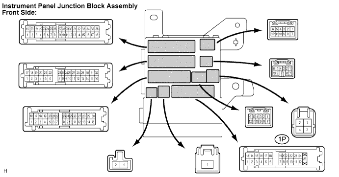
Check the continuity between each of the terminals of the instrument panel junction block assembly connector side and body ground as shown in the chart below.
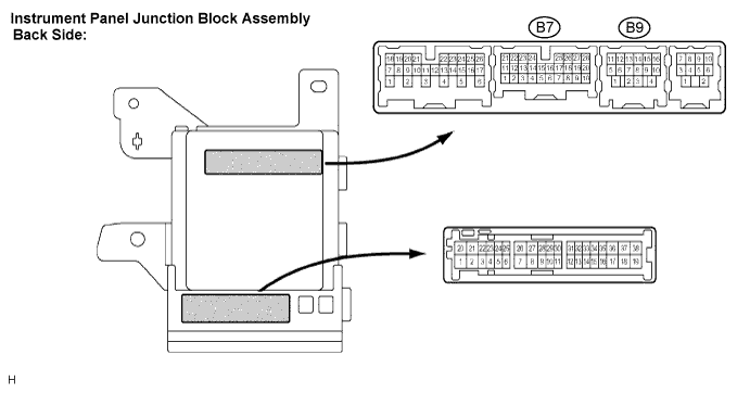
| Tester Connection (Symbols) | Condition | Specified Condition |
| B9-7 - Body ground | Front driver door lock → unlock | Below 1 Ω → 10 kΩ or higher |
| B7-27 - Body ground | Front passenger door lock → unlock | Below 1 Ω → 10 kΩ or higher |
| 1P-5 - Body ground | Rear LH slide door lock → unlock | Below 1 Ω → 10 kΩ or higher |
| B7-5 - Body ground | Rear RH slide door lock → unlock | Below 1 Ω → 10 kΩ or higher |
|
| ||||
| NG | ||
 | ||
| ||
