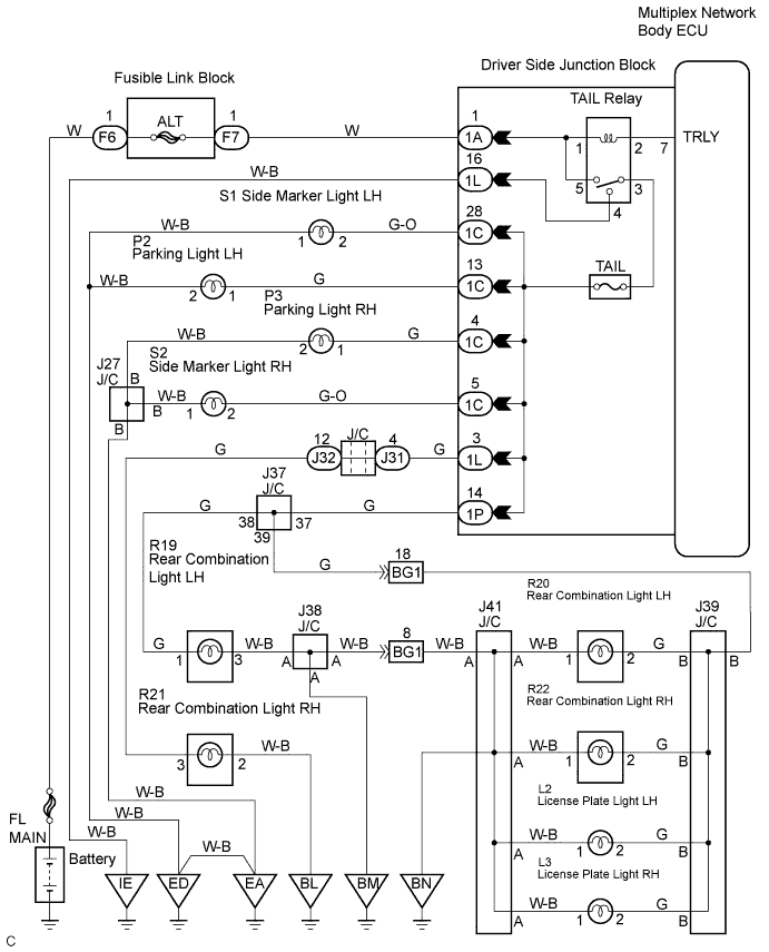
LIGHTING SYSTEM > Taillight Relay Circuit |
| 1.PERFORM ACTIVE TEST USING TECHSTREAM |
Connect the Techstream to the DLC3.
Turn the ignition switch to ON.
Turn the Techstream on.
Enter the following menus: Body Electrical / Body / Active Test.
Check the operation.
| Tester Display | Test Part | Control Range | Diagnostic Note |
| Taillight Relay | Taillight relay | ON / OFF | - |
|
| ||||
| NG | |
 |
| 2.INSPECT TAIL LIGHT RELAY |
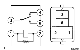 |
Inspect tail light relay continuity.
| Condition | Tester Connection | Specified Condition |
| Always | 1 - 2 3 - 4 | Below 1 Ω |
| Always | 3 - 5 | 10 kΩ or higher |
| Apply B+ between the terminal 1 and 2 | 3 - 5 | Below 1 Ω |
|
| ||||
| OK | |
|
| 3.INSPECT INSTRUMENT PANEL JUNCTION BLOCK ASSEMBLY |
Measure voltage between the terminal 1A-1 and body ground.
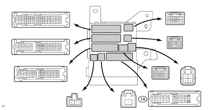
| Tester Connection | Specified Condition |
| 1A-1 - Body ground | 10 to 14 V |
|
| ||||
| OK | |
|
| 4.INSPECT INSTRUMENT PANEL JUNCTION BLOCK ASSEMBLY |
Measure voltage between the each of terminals as shown in the chart below.
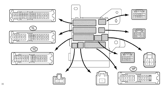
| Tester Connection | Condition | Specified Condition |
| 1L-16 - 1C-4 | Light control switch OFF → TAIL | Below 1 V → 10 to 14V |
| 1L-16 - 1C-5 | Light control switch OFF → TAIL | Below 1 V → 10 to 14V |
| 1L-16 - 1C-13 | Light control switch OFF → TAIL | Below 1 V → 10 to 14V |
| 1L-16 - 1C-28 | Light control switch OFF → TAIL | Below 1 V → 10 to 14V |
| 1L-16 - 1L-3 | Light control switch OFF → TAIL | Below 1 V → 10 to 14V |
| 1L-16 - 1P-14 | Light control switch OFF → TAIL | Below 1 V → 10 to 14V |
|
| ||||
| NG | ||
 | ||
| ||
