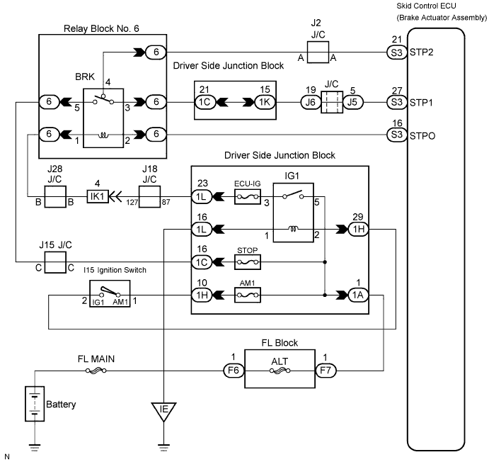
DTC P0571 Stop Light Switch Circuit Malfunction |
| DTC No. | DTC Detection Condition | Trouble Area |
| P0571 | This trouble code is output when the ECM detected the BRK relay error signal from the skid control ECU for 0.2 seconds or more while the dynamic cruise control is in operation. |
|
| 1.CHECK BRK RELAY |
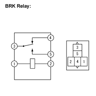 |
Remove the BRK relay from the Relay Block No. 6.
Measure the resistance according to the value(s) in the table below.
| Tester Connection | Specified Condition |
| 1 - 2 | Below 1 Ω |
| 3 - 4 | Below 1 Ω |
| 3 - 5 | 10 kΩ or higher |
Apply battery voltage between terminals 1 and 2.
Measure the resistance according to the value(s) in the table below.
| Tester Connection | Specified Condition |
| 3 - 5 | Below 1 Ω |
|
| ||||
| OK | |
 |
| 2.CHECK HARNESS AND CONNECTOR (BRK RELAY - BATTERY) |
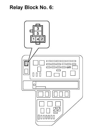 |
Measure the voltage according to the value(s) in the table below.
| Tester Connection | Condition | Specified Condition |
| 5 - Body ground | Always | 10 to 14 V |
| 1 - Body ground | Ignition switch ON | 10 to 14 V |
| 1 - Body ground | Ignition switch off | Below 1 V |
|
| ||||
| OK | |
|
| 3.CHECK HARNESS AND CONNECTOR (BRK RELAY - SKID CONTROL ECU) |
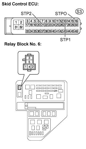 |
Disconnect the skid control ECU connector.
Measure the resistance according to the value(s) in the table below.
| Tester Connection | Condition | Specified Condition |
| 4 - S3-21 (STP2) | Always | Below 1 Ω |
| 4 - Body ground | Always | 10 kΩ or higher |
| 3 - S3-27 (STP1) | Always | Below 1 Ω |
| 3 - Body ground | Always | 10 kΩ or higher |
| 2 - S3-16 (STPO) | Always | Below 1 Ω |
| 2 - Body ground | Always | 10 kΩ or higher |
|
| ||||
| OK | ||
 | ||
| ||
