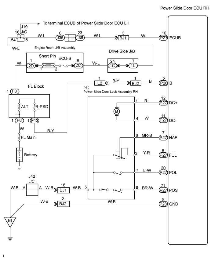
SLIDE DOOR CLOSER SYSTEM > Slide Door Closer RH does not Operate |
| 1.INSPECT FUSE (ECU-B) |
Inspect the ECU-B fuse.
|
| ||||
| OK | |
 |
| 2.INSPECT SLIDE DOOR LOCK |
Check that the slide door fully closes (fully locked) when the door is closed by hand.
|
| ||||
| OK | |
|
| 3.POWER SOURCE RESET |
Disconnect the ECU-B fuse and reconnect it. 10 seconds later, check that the back door closer is operational.
|
| ||||
| NG | |
|
| 4.INSPECT POWER SLIDE DOOR LOCK ASSEMBLY RH |
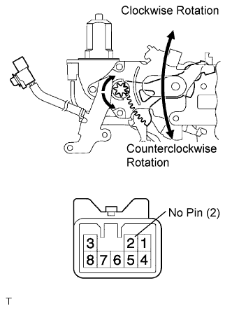 |
Apply battery voltage to the terminals and check the motor operation.
| Measurement Condition | Specified Condition |
| Battery positive (+) → Terminal 1 Battery negative (-) → Terminal 4 | Clockwise Rotation |
| Battery positive (+) → Terminal 4 Battery negative (-) → Terminal 1 | Counterclockwise Rotation |
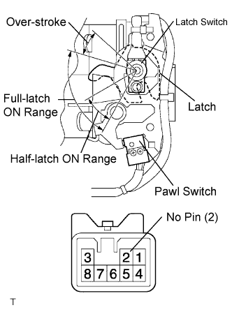 |
At each range of the latch, inspect the resistance of the pawl switch and latch switch.
| Terminal No. | Condition | Specified Condition |
| 5 - 6 | Half-latch ON range | Below 1 Ω |
| 3 - 5 | Full-latch ON range | |
| 5 - 6 3 - 5 | Over-stroke range | More than 10 kΩ |
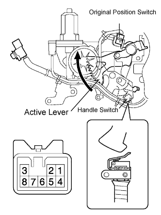 |
Inspect the resistance of the original position switch and handle switch.
| Terminal No. | Original Position Switch | Handle Switch | Result |
| 5 - 8 | OFF (Active lever in original position) | ON (Handle in original position) | 10 kΩ or higher |
| OFF (Handle operated) | |||
| ON (Closer in operation) | ON (Handle in original position) | Below 1 Ω | |
| OFF (Handle operated) | 10 kΩ or higher |
|
| ||||
| OK | |
|
| 5.CHECK WIRE HARNESS (POWER SLIDE DOOR LOCK ASSEMBLY RH - POWER SLIDE DOOR ECU RH) |
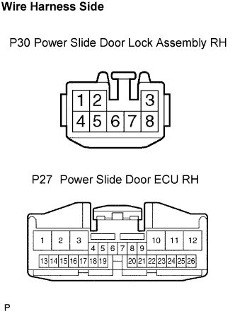 |
Disconnect the P30 door lock and P27 ECU connectors.
Check the resistance between the wire harness connectors.
| Terminal No. | Specified Condition |
| P30-1 - P27-12 (DC+) | Below 1 Ω |
| P30-4 - P27-11 (DC-) | |
| P30-6 - P27-7 (HAF) | |
| P30-3 - P27-8 (FUL) | |
| P30-7 - P27-20 (POL) | |
| P30-8 - P27-21 (POS) |
Check the resistance between the P30 lock connector and body ground.
| Terminal No. | Specified Condition |
| P30-5 - Body ground | Below 1 Ω |
|
| ||||
| OK | ||
 | ||
| ||
