 |
Coat a new O-ring with power steering fluid and install it onto the power steering rack.
RACK AND PINION POWER STEERING GEAR > REASSEMBLY |
| 1. INSTALL RACK STEERING PISTON RING |
|
Coat a new O-ring with power steering fluid and install it onto the power steering rack.
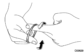
Expand a new rack steering piston ring with your fingers.
Coat a new rack steering piston ring with power steering fluid.
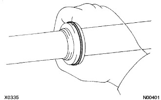 |
Install the rack steering piston ring onto the power steering rack, and settle it down with your fingers.
| 2. INSTALL POWER STEERING CYLINDER TUBE OIL SEAL |
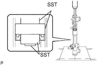 |
Coat a new cylinder tube oil seal lip with power steering fluid.
Using SST and a press, install the cylinder tube oil seal.
| 3. INSTALL POWER STEERING RACK |
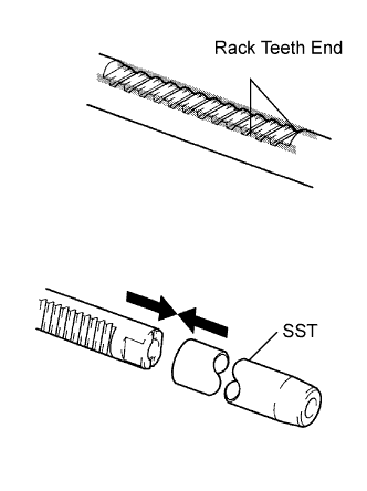 |
Install SST onto the power steering rack.
Coat the SST with power steering fluid.
Install the power steering rack into the rack housing.
Remove the SST.
| 4. INSTALL POWER STEERING RACK BUSH |
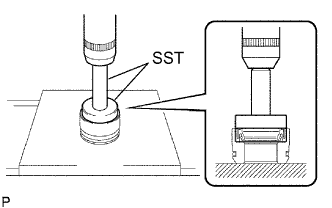 |
Using SST and a press, install the rack bush oil seal onto the rack bush.
Coat a new O-ring with power steering fluid and install it onto the rack bush.
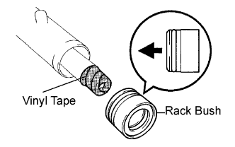 |
To prevent rack bush oil seal lip damage, wind vinyl tape around the rack end, and apply power steering fluid.
Install the rack bush onto the power steering rack.
| 5. INSTALL CYLINDER END STOPPER |
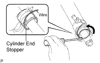 |
Align the installation hole for the wire of the cylinder end stopper with the slot of the rack housing.
Install a new wire into the cylinder end stopper.
Using a screwdriver, turn the cylinder end stopper counterclockwise by 450 +- 50°.
| 6. AIR TIGHTNESS TEST |
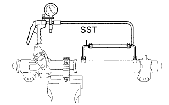 |
Install SST onto the rack housing.
Apply vacuum of 53 kPa (400 mmHg, 15.75 in.Hg) for about 30 seconds.
Check that there is no change in the vacuum.
If there is a change in the vacuum, check the installation of the oil seals.
| 7. INSTALL POWER STEERING CONTROL VALVE UPPER OIL SEAL |
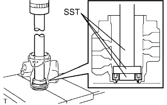 |
Coat a control valve upper bearing and a new control valve upper oil seal with power steering fluid.
Using SST and a press, install the control valve upper oil seal.
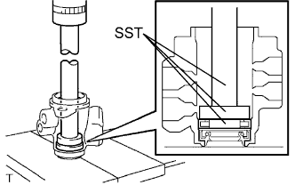 |
Using SST and a press, install the control valve upper bearing.
| 8. INSTALL POWER STEERING CONTROL VALVE |
|
Expand 4 new control valve rings with your fingers.
Coat the 4 control valve rings with power steering fluid.
Install the 4 control valve rings onto the control valve, and settle them down with your fingers.
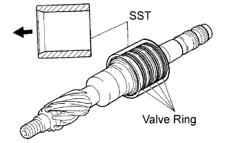 |
Carefully slide the tapered end of SST over the control valve rings until they fit to the control valve.
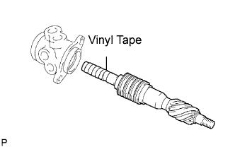 |
To prevent control valve upper oil seal lip damage, wind vinyl tape around the serrated part of the control valve.
Coat the control valve upper oil seal lip with power steering fluid.
Install the control valve onto the control valve housing.
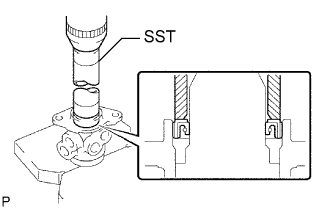 |
Coat a new oil seal lip with power steering fluid.
Using SST and a press, install the oil seal.
Apply grease to the needle roller bearing.
Install a new gasket onto the control valve housing.
Wind vinyl tape around the serrated part of the control valve.
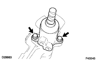 |
Install the control valve w/ control valve housing onto the rack housing with the 2 bolts.
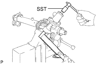 |
Using SST, hold the control valve rotation and install a new lock nut.
Apply sealant to 2 or 3 threads of the rack housing cap.
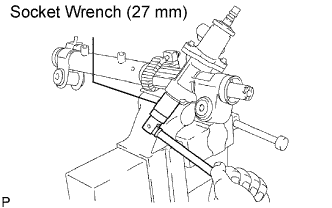 |
Using a socket wrench (27 mm), install the rack housing cap.
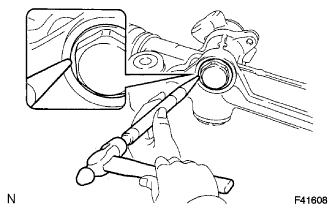 |
Using a punch and a hammer, stake the rack housing cap and rack housing.
| 9. INSTALL RACK GUIDE |
Install the rack guide.
Install the compression spring.
Apply sealant to 2 or 3 threads of the rack guide spring cap.
Temporarily install the rack guide spring cap.
| 10. INSTALL TOTAL PRELOAD |
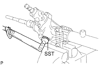 |
To prevent the steering rack teeth from damaging the oil seal lip, temporarily install the RH and LH steering rack ends sub-assembly.
Using SST, torque the rack guide spring cap.
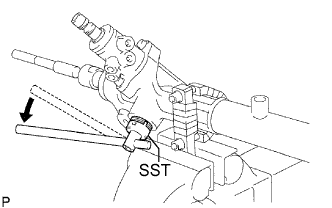 |
Using SST, loosen the rack guide spring cap.
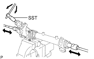 |
Using SST, turn the control valve to the right and left 1 or 2 times.
Using SST, loosen the rack guide spring cap until the compression spring is not functioning.
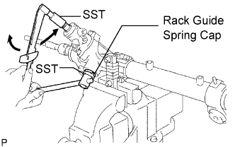 |
Using SST and a torque wrench, tighten the rack guide spring cap until the preload is within specification.
Apply sealant to 2 or 3 threads of the rack guide spring cap nut.
Temporarily install the rack guide spring cap nut.
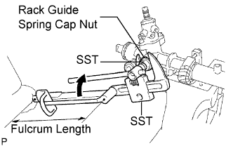 |
Using SST, hold the rack guide spring cap and using another SST, torque the rack guide spring cap nut.
Precheck the total preload.
Remove the RH and LH steering rack ends sub-assembly.
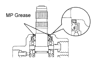 |
Apply MP grease to the control valve, as shown in the illustration.
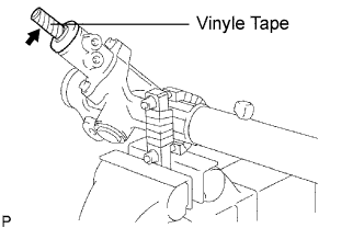 |
Wind vinyl tape around the serrated part of the control valve.
Install the dust cover onto the control valve housing.
| 11. INSTALL STEERING RACK END SUB-ASSEMBLY |
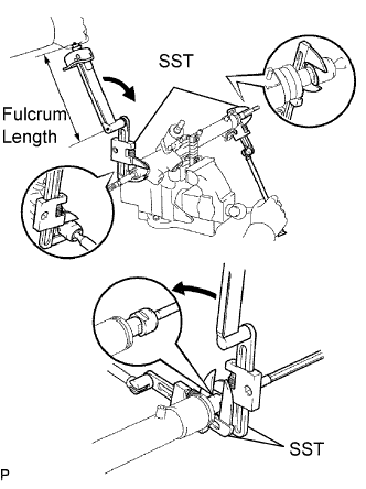 |
Install 2 new claw washers, and temporarily install the 2 steering rack end sub-assembly.
Using 2 SST, install the 2 rack end sub-assembly.
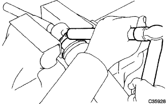 |
Using a brass bar and a hammer, stake the 2 claw washers.
| 12. INSPECT STEERING RACK END SUB-ASSEMBLY |
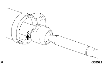 |
Ensure that the rack end sub-assembly hole is not clogged with grease.
| 13. INSTALL STEERING RACK BOOT NO.2 |
| 14. INSTALL STEERING RACK BOOT NO.1 |
| 15. INSTALL STEERING RACK BOOT NO.2 CLAMP |
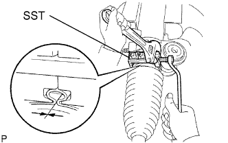 |
Using SST, tighten the rack boot No.2 clamp, as shown in the illustration.
| 16. INSTALL STEERING RACK BOOT NO.1 CLAMP |
| 17. INSTALL STEERING RACK BOOT CLIP |
Using pliers, install the 2 rack boot clips.
| 18. INSTALL TIE ROD ASSEMBLY LH |
Screw the lock nut and tie rod assembly onto the rack end sub-assembly until the matchmarks are aligned.
| 19. INSTALL TIE ROD ASSEMBLY RH |
| 20. INSTALL STEERING LEFT TURN PRESSURE TUBE |
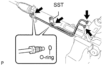 |
Coat 2 new O-rings with power steering fluid and install them onto the left turn pressure tube.
Using SST, install the left turn pressure tube onto the power steering gear assembly.
| 21. INSTALL STEERING RIGHT TURN PRESSURE TUBE |
| 22. INSTALL RETURN TUBE NO.2 |
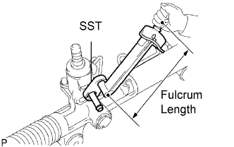 |
Using SST, install the return tube No. 2.