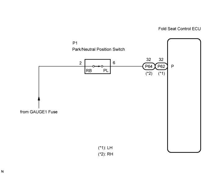
REAR NO. 2 SEAT ASSEMBLY (w/ Power Stowing Function) > Park / Neutral Position Switch Circuit |
| 1.INSPECT FOLD SEAT CONTROL ECU |
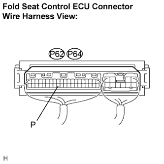 |
Remove the fold seat control ECU with connectors still connected.
Turn the ignition switch ON.
Measure the voltage according to the value(s) in the table below.
| Tester Connection (Symbols) | Condition | Specified Condition |
| P62-32 (P) - body ground | Park/Neutral position switch: P position | 10 to 14 V |
| P62-32 (P) - body ground | Park/Neutral position switch: except P position | Below 2 V |
| Tester Connection (Symbols) | Condition | Specified Condition |
| P64-32 (P) - body ground | Park/Neutral position switch: P position | 10 to 14 V |
| P64-32 (P) - body ground | Park/Neutral position switch: except P position | Below 2 V |
|
| ||||
| NG | |
 |
| 2.CHECK HARNESS AND CONNECTOR (FOLD SEAT CONTROL ECU - PARK/NEUTRAL POSITION SWITCH) |
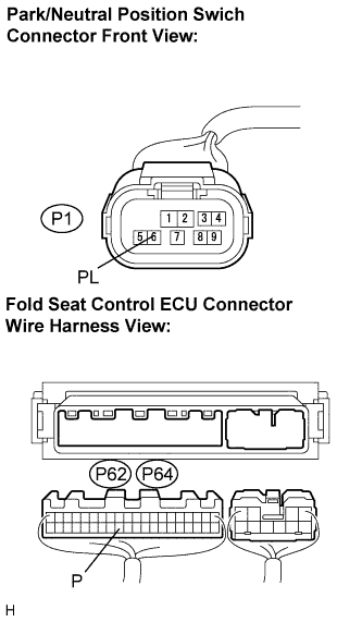 |
Disconnect the connector from the park/neutral position switch.
Disconnect the connectors from the fold seat control ECU.
Measure the resistance according to the value(s) in the table below.
| Tester Connection (Symbols) | Condition | Specified Condition |
| P62-32 (P) - P1-6 (PL) | Always | Below 1 Ω |
| P62-32 (P) - Body ground | Always | 10 kΩ or higher |
| Tester Connection (Symbols) | Condition | Specified Condition |
| P64-32 (P) - P1-6 (PL) | Always | Below 1 Ω |
| P64-32 (P) - Body ground | Always | 10 kΩ or higher |
|
| ||||
| OK | |
|
| 3.INSPECT PARK/NEUTRAL POSITION SWITCH |
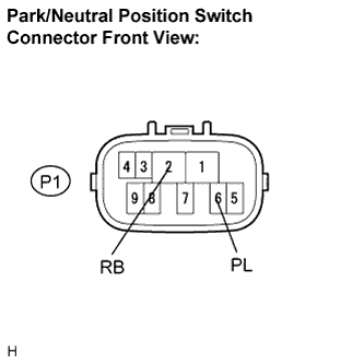 |
Remove the park/neutral position switch.
Measure the resistance according to the value(s) in the table below.
| Tester connection (Symbols) | Condition | Specified condition |
| P1-2 (RB) - P1-6 (PL) | Park/neutral position switch: except P position | 10 kΩ or higher |
| P1-2 (RB) - P1-6 (PL) | Park/neutral position switch: P position | Below 1 Ω |
|
| ||||
| OK | |
|
| 4.CHECK HARNESS AND CONNECTOR (PARK/NEUTRAL POSITION SWITCH - BATTERY) |
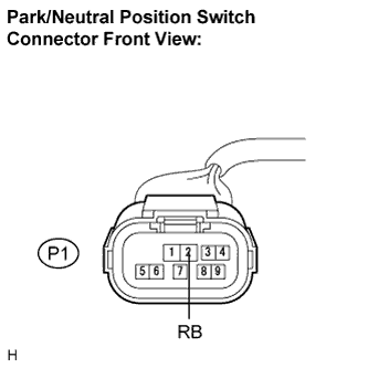 |
Measure the voltage according to the value(s) in the table below.
| Tester connection (Symbols) | Condition | Specified condition |
| P1-2 (RB) - Body ground | Ignition switch: OFF | Below 1 V |
| P1-2 (RB) - Body ground | Ignition switch: ON | 10 to 14 V |
|
| ||||
| OK | ||
 | ||
| ||
