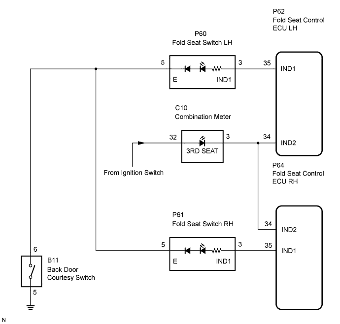
REAR NO. 2 SEAT ASSEMBLY (w/ Power Stowing Function) > Indicator Circuit |
| 1.INSPECT FOLD SEAT SWITCH |
Remove the fold seat switch.
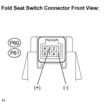 |
Disconnect the connector from the fold seat switch.
Connect the positive (+) lead from the battery terminal 3 and negative (-) lead to terminal 5, and check that the indicator light comes on.
|
| ||||
| OK | |
 |
| 2.CHECK HARNESS AND CONNECTOR (FOLD SEAT CONTROL ECU - FOLD SEAT SWITCH) |
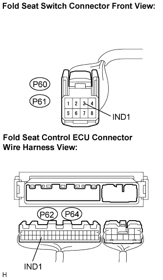 |
Disconnect the connector from the fold seat control ECU.
Measure the resistance according to the value(s) in the table below.
| Tester Connection (Symbols) | Condition | Specified Condition |
| P62-35 (IND1) - P60-3 (IND1) | Always | Below 1 Ω |
| P62-35 (IND1) - Body ground | Always | 10 kΩ or higher |
| Tester Connection (Symbols) | Condition | Specified Condition |
| P64-35 (IND1) - P61-3 (IND1) | Always | Below 1 Ω |
| P64-35 (IND1) - Body ground | Always | 10 kΩ or higher |
|
| ||||
| OK | |
|
| 3.CHECK HARNESS AND CONNECTOR (FOLD SEAT SWITCH - BACK DOOR COURTESY SWITCH) |
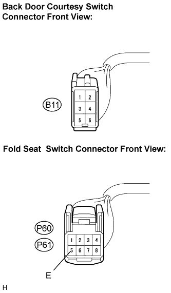 |
Disconnect the connector from the back door courtesy switch.
Measure the resistance according to the value(s) in the table below.
| Tester Connection (Symbols) | Condition | Specified Condition |
| P60-5 (E) - B11-6 | Always | Below 1 Ω |
| P60-5 (E) - Body ground | Always | 10 kΩ or higher |
| Tester Connection (Symbols) | Condition | Specified Condition |
| P61-5 (E) - B11-6 | Always | Below 1 Ω |
| P61-5 (E) - Body ground | Always | 10 kΩ or higher |
|
| ||||
| OK | |
|
| 4.INSPECT BACK DOOR COURTESY SWITCH |
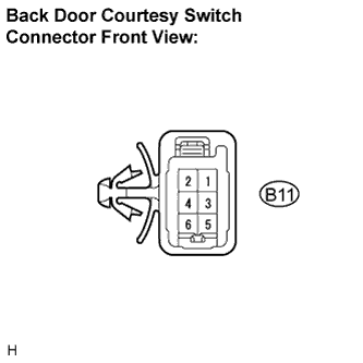 |
Measure the resistance according to the value(s) in the table below.
| Tester Connection | Condition | Specified Condition |
| B11-6 - B11-5 | Back door courtesy switch: OFF | 10 kΩ or higher |
| B11-6 - B11-5 | Back door courtesy switch: ON | Below 1 Ω |
|
| ||||
| OK | |
|
| 5.CHECK HARNESS AND CONNECTOR (BACK DOOR COURTESY SWITCH - BODY GROUND) |
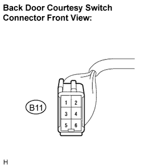 |
Measure the resistance according to the value(s) in the table below.
| Tester Connection | Condition | Specified Condition |
| B11-5 - Body ground | Always | Below 1 Ω |
|
| ||||
| OK | ||
 | ||
| ||
| 6.CHECK HARNESS AND CONNECTOR (COMBINATION METER - BATTERY) |
Remove the combination meter.
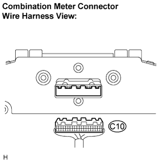 |
Disconnect the connector from the combination meter.
Measure the voltage according to the value(s) in the table below.
| Tester Connection | Condition | Specified Condition |
| C10-32 - Body ground | Ignition switch: OFF | Below 1 V |
| C10-32 - Body ground | Ignition switch: ON | 10 to 14 V |
|
| ||||
| OK | |
|
| 7.CHECK HARNESS AND CONNECTOR (COMBINATION METER - FOLD SEAT CONTROL ECU) |
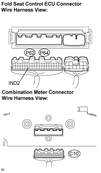 |
Disconnect the connector from the fold seat control ECU.
Measure the resistance according to the value(s) in the table below.
| Tester Connection (Symbols) | Condition | Specified Condition |
| C10-3 - P62-34 (IND2) | Always | Below 1 Ω |
| C10-3 - Body ground | Always | 10 kΩ or higher |
| Tester Connection (Symbols) | Condition | Specified Condition |
| C10-3 - P64-34 (IND2) | Always | Below 1 Ω |
| C10-3 - Body ground | Always | 10 kΩ or higher |
|
| ||||
| OK | |
|
| 8.INSPECT COMBINATION METER (3rd SEAT INDICATOR LIGHT) |
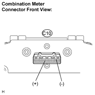 |
Connect the positive (+) lead from the battery terminal 32 and negative (-) lead to terminal 3, and check that the indicator light comes on.
|
| ||||
| OK | ||
| ||
| ||
