Home › BODY ELECTRICAL › DOOR LOCK › SLIDE DOOR LOCK

SLIDE DOOR LOCK > INSPECTION

for Preparation Click here


1. INSPECT SLIDE DOOR LOCK ASSEMBLY LH


    B068914E01
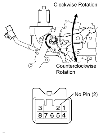
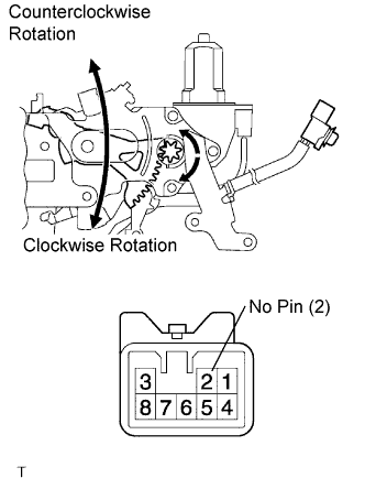
  1. Apply battery voltage to the terminals and check the motor operation.

    OK:
    Measurement Condition
    Specified Condition
    Battery positive (+) → Terminal 1
    Battery negative (-) → Terminal 4
    Clockwise Rotation
    Battery positive (+) → Terminal 4
    Battery negative (-) → Terminal 1
    Counterclockwise Rotation

    If the result is not as specified, replace the door lock assembly.


    B068882E01
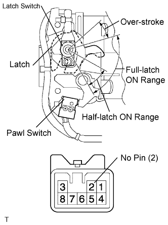
  1. At each range of the latch, inspect the resistance of the pawl switch and latch switch.

    Resistance:
    Terminal No.
    Condition
    Specified Condition
    5 - 6
    Half-latch ON range
    Below 1 Ω
    3 - 5
    Full-latch ON range
    5 - 6
    3 - 5
    Over-stroke range
    More than 10 kΩ

    If the result is not as specified, replace the door lock assembly.


    B068881E01
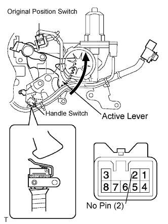
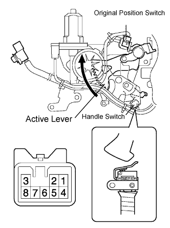
  1. Inspect the resistance of the original position switch and handle switch.

    Resistance:

    Terminal No.
    Original Position
    Switch Handle Switch
    Specified Condition
    5 - 8
    OFF (Active lever in original position)
    ON (Handle in original position)
    10 kΩ or higher
    OFF (Handle operated)
    ON (Closer in operation)
    ON (Handle in original position)
    Below 1 Ω
    OFF (Handle operated)
    10 kΩ or higher

    If the result is not as specified, replace the door lock assembly.


2. INSPECT SLIDE DOOR LOCK ASSEMBLY RH


    B068879E01
  1. Apply battery voltage to the terminals and check the motor operation.

    OK:
    Measurement Condition
    Specified Condition
    Battery positive (+) → Terminal 1
    Battery negative (-) → Terminal 4
    Clockwise Rotation
    Battery positive (+) → Terminal 4
    Battery negative (-) → Terminal 1
    Counterclockwise Rotation

    If the result is not as specified, replace the door lock assembly.


    B068915E01
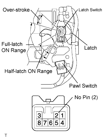
  1. At each range of the latch, inspect the resistance of the pawl switch and latch switch.

    Resistance:
    Terminal No.
    Condition
    Specified Condition
    5 - 6
    Half-latch ON range
    Below 1 Ω
    3 - 5
    Full-latch ON range
    5 - 6
    3 - 5
    Over-stroke range
    More than 10 kΩ

    If the result is not as specified, replace the door lock assembly.


    B068916E01
  1. Inspect the resistance of the original position switch and handle switch.

    Resistance:

    Terminal No.
    Original Position Switch
    Handle Switch
    Result
    5 - 8
    OFF (Active lever in original position)
    ON (Handle in original position)
    10 kΩ or higher
    OFF (Handle operated)
    ON (Closer in operation)
    ON (Handle in original position)
    Below 1 Ω
    OFF (Handle operated)
    10 kΩ or higher

    If the result is not as specified, replace the door lock assembly.