BODY PANEL FRONT FENDER APRON ASSEMBLY REPLACEMENT (PATTERN 2)
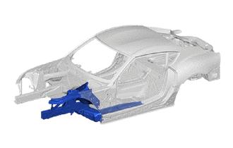
REMOVE THE ADHESIVE
Detach any mechanical connecting elements where required.
Heat the adhesive flange with a hot air blower.
- NOTICE:
-
Do not exceed the maximum object temperature of 250°C.
Use pliers or a chisel to peel off the component.
- NOTICE:
-
Do not damage adjacent components.
Remove adhesive residue from the adhesive flange.
REMOVAL
| Symbol Meaning | |
|---|---|

|
Remove Weld Points |

|
Remove Weld Points |

|
Cut with Disc Sander etc. |

|
Cut Location |
Mark and perform the separating cut (1) in accordance with the schematic diagram.
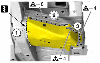
Remove the weld points in areas (2) and (3).
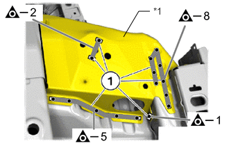
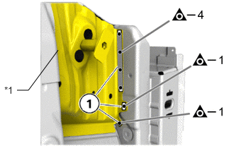
| *1 | FRONT SIDE MEMBER REINFORCEMENT SUB-ASSY NO.2 |
Remove the weld points in areas (1).
Remove the front side member reinforcement sub-assy No.2.
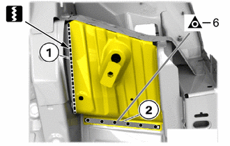
Mark and perform the separating cut (1) in accordance with the schematic diagram.
Remove the weld points in area (2).
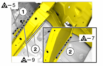
| *1 | TORQUE BOX FRONT |
Remove the weld points in areas (1).
Remove the torque box front.
Remove the weld points and adhesive in areas (1) and (2).
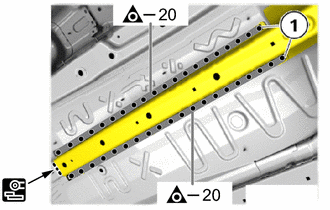
Remove the weld points and adhesive in area (1).
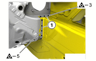
Remove the weld points in areas (1).
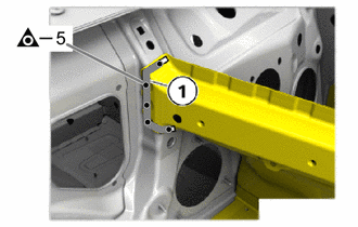
Remove the weld points in area (1).
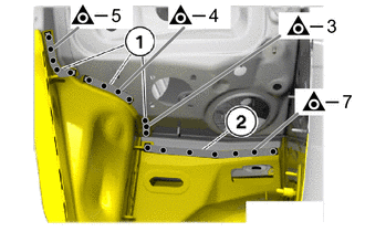
Remove the weld points and adhesive in area (1).
Remove the weld points in area (2).
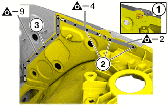
Remove the ball pin (1).
Remove the weld points in areas (2).
Remove the weld points and adhesive in area (3).
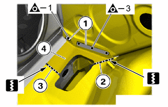
Remove the weld points in areas (1).
Mark and carry out the separating cuts according to the specified dimensions in the areas (2) and (3).
- HINT:
-
Disconnect the outer panel alone in the area (4).
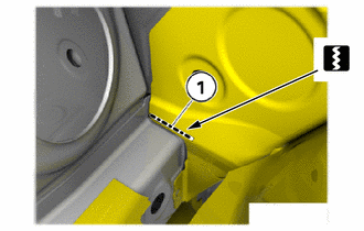
Mark and perform the separating cut (1) in accordance with the schematic diagram.
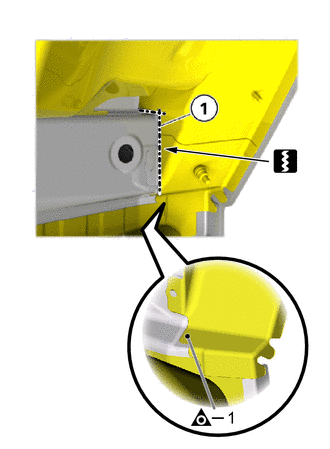
Mark and perform the separating cut (1) in accordance with the schematic diagram.
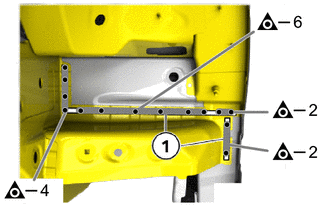
Remove the weld points in areas (1).
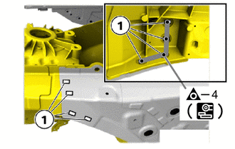
Remove the weld points in the areas (1) from the inside of the wheel arch with the belt sander.
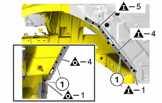
Remove the weld points in areas (1).
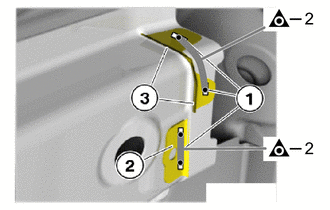
Remove the weld points in areas (1).
Remove the sections (2) and (3).
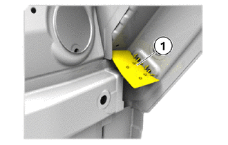
Remove the foamed sealing material (1).
PREPARE NEW PART
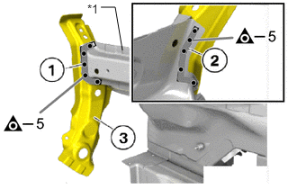
| *1 | W/FRONT SIDE MEMBER APRON ASSY |
Remove the weld points in area (1).
Remove the weld points and adhesive in area (2).
Remove the (3) from the new part of the w/front side member apron assy.
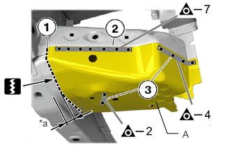
| *a | 20 mm (0.79 in.) |
Mark and carry out the separating cut (1) in accordance with the specified dimension.
Remove the weld points in the areas (2)and (3).
Remove the A from the new part of the w/front side member apron assy.
- HINT:
-
Separated section of the outer connection is required to make the reinforcement plate.
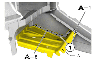
Remove the weld points in areas (1).
Remove the A from the new part of the w/front side member apron assy.
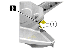
Cut off panel sections (1) in accordance with the schematic diagram from the new part of the w/front side member apron assy.
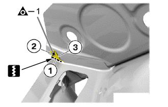
Mark and perform the separating cut (1) in accordance with the schematic diagram.
- HINT:
-
Disconnect only the outer panel.
Remove the weld points in the area (2).
Remove section (3) from the new part of the w/front side member apron assy.
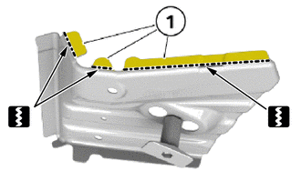
Mark and cut off sections (1) from the new part of the outer connection reinforcement in accordance with the schematic diagram.
PREPARE REINFORCEMENT PLATE
- HINT:
- ·
Schematic diagram is for example purposes.
·Some parts may differ in certain details.
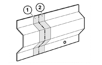
Maintain a distance of approximately one to maximum two material thicknesses at the separating cut to ensure welding with the reinforcement plate.
Clean both sides of the connection faces on the new part (1) and the body (2) .
Coat insides with welding primer.
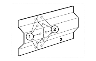
Drill holes (1) and (2) with a diameter of 8 mm (0.31 in.) at a distance of 25 mm (0.98 in.) from each other.
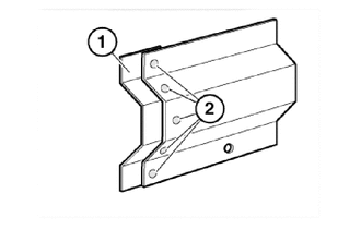
Produce a reinforcement plate (1) with a minimum length of 40 mm (1.57 in.) from the trim of the new part.
Smooth both sides of the reinforcement plate (1) and coat with a welding primer.
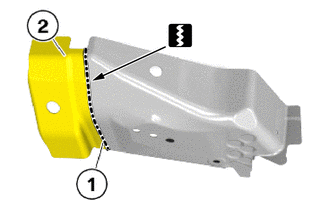
Mark and carry out separating cut (1) on the new part of the outer bottom connection according to the separating cut of the new part of the left front end.
Remove section (2).
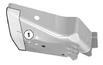
Make reinforcement plate (1) from the panel section of the new part preparation process of the left front end.
INSTALLATION
| Symbol Meaning | |
|---|---|

|
Plug Weld |

|
Plug Weld |

|
Fillet Weld |
Align and position w/front side member apron assy on the vehicle.
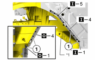
| *1 | W/FRONT SIDE MEMBER APRON ASSY |
Weld the front fender apron assy in the areas (1).
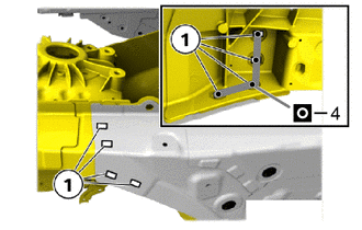
Weld the w/front side member apron assy in the areas (1).
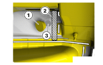

|
Foamed Sealing Material |
Remove the plug (1).
Protect area of the foamed sealing material (2) with compressed air against risk of fire during the welding works described below.
- CAUTION:
-
Danger of injury!:Swirling dirt particles caused by compressed air.
- ·
Collect dirt particles, e.g. when blowing out, use cloth to do so.
·Wear safety goggles.
- HINT:
-
Run in the air gun through the bore hole (3).
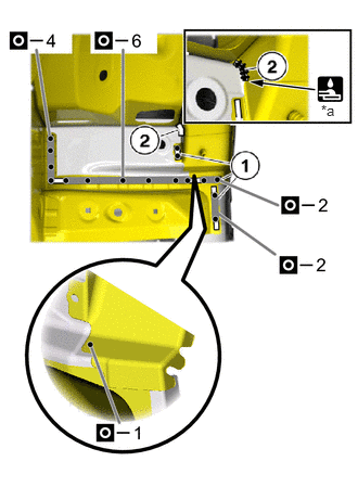
| *a | 25 mm (0.98 in.) |
Weld the w/front side member apron assy in the areas (1) and (2) .
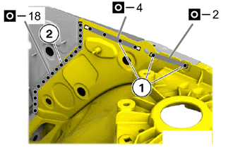
Weld the w/front side member apron assy in the areas (1) and (2) .
| *a | 40 mm (1.57 in.) |
Weld the w/front side member apron assy in the area (1).
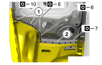
Weld the w/front side member apron assy in the areas (1) and (2) .
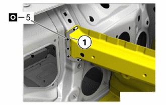
Weld the w/front side member apron assy in the area (1) .
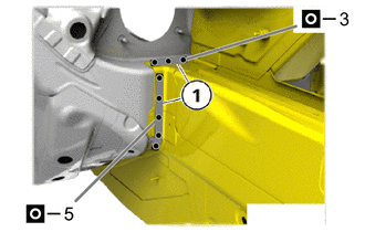
Weld thew/front side member apron assy in the areas (1).
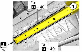
| *a | Ultra High Strength Steel Welding Point |
| *b | 40 mm (1.57 in.) |
Weld the w/front side member apron assy in the areas (1).
When welding 2 panels together including 1180 MPa ultra high strength steel.
| Plug weld | Plug diameter | 8 mm (0.31 in.) |
| Wire type | AWS A5.18 ER70S-3 | |
| Shield gas | Metal active gas |
- NOTICE:
-
Be sure to use Metal active gas (Ar 80% + CO2 20%) as the shield gas when plug welding.Sufficient weld strength cannot be assured when using 100% CO2 shield gas.
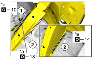
| *a | Ultra High Strength Steel Welding Point |
Weld the w/front side member apron assy in the areas (1) and (2).
When welding 2 panels together including 980 MPa ultra high strength steel.
| Plug weld | Plug diameter | 8 mm (0.31 in.) |
| Wire type | AWS A5.18 ER70S-3 | |
| Shield gas | Metal active gas |
- NOTICE:
-
Be sure to use Metal active gas (Ar 80% + CO2 20%) as the shield gas when plug welding.Sufficient weld strength cannot be assured when using 100% CO2 shield gas.
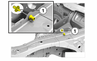
Install the ball pin (1).
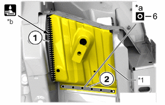
| *1 | TORQUE BOX FRONT |
| *a | Ultra High Strength Steel Welding Point |
| *b | 265 mm (10.43 in.) |
Weld the torque box front in the areas (1) and (2).
- HINT:
-
Weld using MAG weld seam in the area (1).
When welding 2 panels together including 1180 MPa ultra high strength steel.
| Plug weld | Plug diameter | 8 mm (0.31 in.) |
| Wire type | AWS A5.18 ER70S-3 | |
| Shield gas | Metal active gas |
- NOTICE:
-
Be sure to use Metal active gas (Ar 80% + CO2 20%) as the shield gas when plug welding.Sufficient weld strength cannot be assured when using 100% CO2 shield gas.
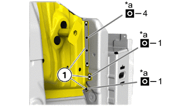
| *a | Ultra High Strength Steel Welding Point |
Weld the torque box front in the areas (1).
When welding 2 panels together including 1180 MPa ultra high strength steel.
| Plug weld | Plug diameter | 8 mm (0.31 in.) |
| Wire type | AWS A5.18 ER70S-3 | |
| Shield gas | Metal active gas |
- NOTICE:
-
Be sure to use Metal active gas (Ar 80% + CO2 20%) as the shield gas when plug welding.Sufficient weld strength cannot be assured when using 100% CO2 shield gas.
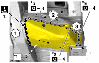
| *1 | FRONT SIDE MEMBER REINFORCEMENT SUB-ASSY NO.2 |
| *a | Ultra High Strength Steel Welding Point |
| *b | 200 mm (7.87 in.) |
Weld the front side member reinforcement sub-assy No.2 in the areas (1), (2) and (3).
- HINT:
-
Weld using MAG weld seam in the area (1).
When welding 2 panels together including 1180 MPa ultra high strength steel.
| Plug weld | Plug diameter | 8 mm (0.31 in.) |
| Wire type | AWS A5.18 ER70S-3 | |
| Shield gas | Metal active gas |
- NOTICE:
-
Be sure to use Metal active gas (Ar 80% + CO2 20%) as the shield gas when plug welding.Sufficient weld strength cannot be assured when using 100% CO2 shield gas.
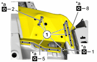
| *a | Ultra High Strength Steel Welding Point |
Weld the front side member reinforcement sub-assy No.2 in the areas (1).
When welding 2 panels together including 1180 MPa ultra high strength steel.
| Plug weld | Plug diameter | 8 mm (0.31 in.) |
| Wire type | AWS A5.18 ER70S-3 | |
| Shield gas | Metal active gas |
- NOTICE:
-
Be sure to use Metal active gas (Ar 80% + CO2 20%) as the shield gas when plug welding.Sufficient weld strength cannot be assured when using 100% CO2 shield gas.
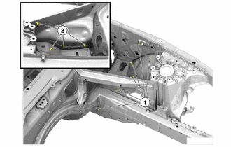
Weld coarse thread bolts (1) and (2) to the new part.
- HINT:
-
Take the quantity and position from the component to be replaced.
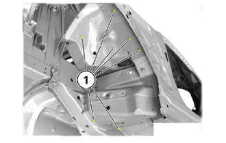
Weld coarse thread bolt (1) on the new part.
- HINT:
-
Take the quantity and position from the component to be replaced.
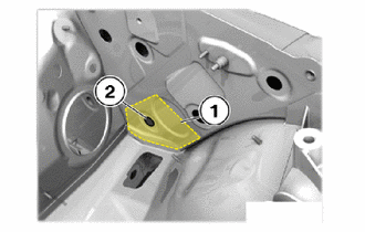
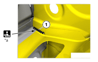
Apply the foamed sealing material to the area (1).
- HINT:
-
Insert the spraying pipe from the bore hole (2).
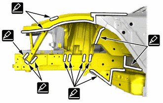
Apply seam seal to the rivets.
- Expendable materials:
Seam Seal 310ml 08826-WA220
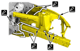
Apply seam seal to the rivets.
- Expendable materials:
Seam Seal 310ml 08826-WA220
After welding, apply body sealer and undercoating to the corresponding parts. (See the painting/coating)
After applying the top coat, apply anti-rust agent to the internal panel portion of the closed section structural weld points.
POSTPROCESSES
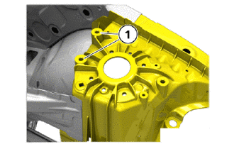
At the bolting points (1) of the top stiffening plate strut it is necessary to cut the M10 (pitch:1.5) thread.
Renew screws.