BODY PANEL FRONT SIDE MEMBER ASSEMBLY REPLACEMENT
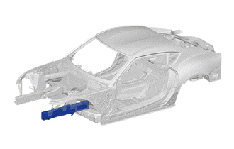
REMOVE THE ADHESIVE
Detach any mechanical connecting elements where required.
Heat the adhesive flange with a hot air blower.
- NOTICE:
-
Do not exceed the maximum object temperature of 250°C.
Use pliers or a chisel to peel off the component.
- NOTICE:
-
Do not damage adjacent components.
Remove adhesive residue from the adhesive flange.
REMOVAL
| Symbol Meaning | |
|---|---|

|
Remove Weld Points |

|
Cut Location |
Remove the self-tapping screws and adhesive connections in the areas (1).
Remove the self-tapping screws and adhesive connections in the areas (2).
Remove the self-tapping screws and adhesive connections in area (3).
Remove the rivets and adhesive connections in area (4).
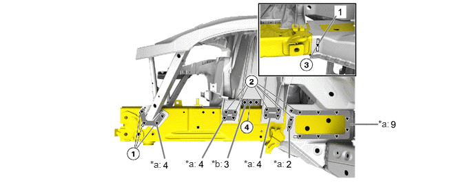
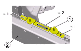
| *a | Self-tapping Screw | *b | Rivet |
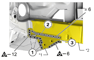
| *a | Self-tapping Screw |
| *1 | FRONT SIDE MEMBER PLATE NO.4 |
| *2 | FRONT SIDE MEMBER SUB-ASSY |
Remove the weld points in areas (1).
Remove the self-tapping screws and adhesive connections in area (2).
Remove the front side member plate No.4 (3) of the front side member sub-assy.
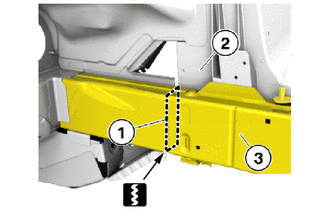
Mark and make the separating cut (1) as shown.
- NOTICE:
-
Do not damage the front fender apron sub-assy (2).
Remove the section (3) of the front side member sub-assy.
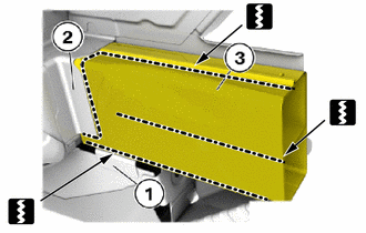
Separate section of the front side member sub-assy in the marked area.
- NOTICE:
-
Do not damage the (1) and the (2).
Remove the section (3).
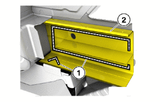

|
Adhesive |
Remove the adhesive (1).
Remove section (2) of the front side member sub-assy.
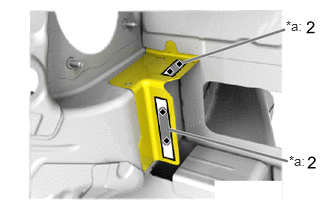
| *a | Rivet |
Remove the bonded rivet connections from the used part in the marked areas from the inside with a belt sander.
- HINT:
-
The sanding belt of the belt sander should be 12 mm (0.47 in.) wide.
PREPARE NEW PART
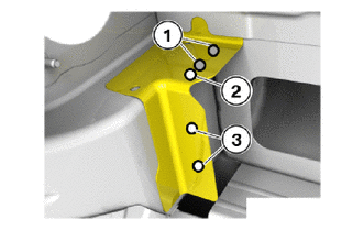
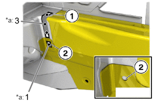
Seal the holes (1) as part of the welding method.
Recreate the hole (2) and drill out to φ6.8 mm (0.27 in.).
Drill out holes (3) to φ6.8 mm (0.27 in.).
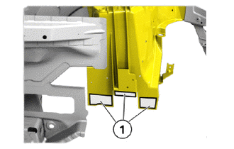
Remove adhesive residue on the bonding surface (1) of the front fender apron sub-assy.
- NOTICE:
-
Do not damage the front fender apron sub-assy.
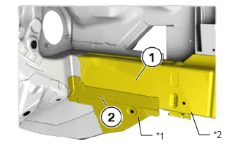
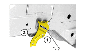
| *1 | FRONT SIDE MEMBER PLATE NO.4 |
| *2 | FRONT SIDE MEMBER SUB-ASSY |
Adjust the front side member sub-assy (1) and the front side member plate No.4 (2) of the inner engine support.
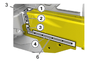
Drill holes in the areas (1) and (2) in the front side member sub-assy.
Drill out holes to φ6.8 mm (0.27 in.).
Transfer the hole pattern in the area (3) of the front side member plate No.4 to the front side member reinforcement No.1 and to the front side member sub-assy. (See the introduction)
Drill out holes to φ6.8 mm (0.27 in.).
Drill holes in the area (4) to φ6.8 mm (0.27 in.).
- HINT:
-
Select the number and position the holes in the same way as for the self-tapping screws in standard production.
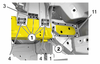
Drill out holes in the areas (1) on the front fender apron sub-assy to φ6.8 mm (0.27 in.).
Transfer the hole pattern in the area (1) from the used part to the front side member sub-assy. (See the introduction)
Drill out holes to φ6.8 mm (0.27 in.).
Drill out holes in the areas (2) on the front side member reinforcement sub-assy to φ6.8 mm (0.27 in.).
Transfer the hole pattern in the area (2) from the used part to the front side member sub-assy. (See the introduction)
Drill out holes to φ6.8 mm (0.27 in.).
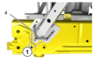
Drill out holes in the areas (1) in the front fender apron sub-assy to φ6.8 mm (0.27 in.).
Transfer the hole pattern in the marked area from the used part to the front side member sub-assy. (See the introduction)
Drill out holes to φ6.8 mm (0.27 in.).
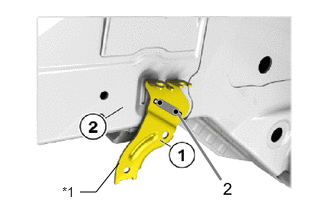
| *1 | STRUT BAR BRACKET REINFORCEMENT |
Transfer the hole pattern in the marked area from the used part to the holder of the strut bar bracket reinforcement (1). (See the introduction)
Drill out holes to φ6.8 mm (0.27 in.).
Transfer the hole pattern in the area (2) from the used part to the front side member sub-assy. (See the introduction)
Drill out holes to φ6.8 mm (0.27 in.).
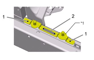
| *1 | DSC BRACKET |
Transfer the hole pattern in the marked area from the used part to the holder of the DSC bracket (1) and to the front side member sub-assy (2). (See the introduction)
Drill out holes to φ6.8 mm (0.27 in.).
PREPARE THE ALUMINIUM SURFACE (USED PART) FOR STRUCTURAL BONDING
Remove coarse contamination from the bonding surfaces using solvent cleaner R2.
- Expendable materials:
Cleaner R2 500ml 08879-WA010
Clean the bonding surfaces using solvent cleaner R1.
- Expendable materials:
Cleaner R1 100ml, Bottle 08833-WA050
Remove oxide layers or paint from bonding surfaces using a stainless steel wire brush or sandpaper with 120 grain.
- HINT:
-
The surface must be down to the bare metal.
Clean the bonding surfaces using solvent cleaner R1.
- Expendable materials:
Cleaner R1 100ml, Bottle 08833-WA050
Allow cleaned surfaces to dry for approximately 5 min.
- HINT:
-
The bonding surfaces must be completely dry.
Flame spray the bonding surfaces with primer P2.
- HINT:
- ·
Go over the bonding surfaces slowly with the flame.
·Flaming with the blue part of the flame must be avoided.
·Condensation water appears on the area that is still uncoated. The condensation water in the line of the flame must evaporate completely.
- Expendable materials:
Primer P2 50ml, Gas cartridge 08833-WA240
Immediately following flame spraying, coat the bonding surfaces that are still warm (approximately 50°C) with primer P1. Apply the primer P1 with a brush, cotton ball or similar item.
- Expendable materials:
Primer P1 50ml, Bottle 08833-WA030
Allow the bonding surfaces to dry for approximately 5 min.
PREPARE THE STEEL SURFACE (USED PART AND NEW PART) FOR STRUCTURAL BONDING
Remove coarse contamination from the bonding surfaces using solvent cleaner R2.
- Expendable materials:
Cleaner R2 500ml 08879-WA010
Clean the bonding surfaces using solvent cleaner R1.
- Expendable materials:
Cleaner R1 100ml, Bottle 08833-WA050
Grind the bonding surface down to the bare metal.
Clean the bonding surface with cleaning agent R1.
- Expendable materials:
Cleaner R1 100ml, Bottle 08833-WA050
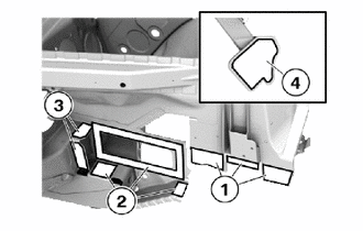
Prepare the front fender apron sub-assy (aluminium used part) in the areas (1) for bonding with the front side member sub-assy (aluminium new part).
Prepare the connecting plate of the front outer engine support in the areas (2) for steel bonding.
Prepare the connecting plate of the front top engine support in the areas (3) for steel bonding to the inside.
Prepare the front fender apron sub-assy (aluminium used part) in the area (4) for bonding with the front side member sub-assy (aluminium new part).
PREPARE THE ALUMINIUM SURFACE (NEW PART) FOR STRUCTURAL BONDING
Do not sand the bonding surfaces.
Remove coarse contamination from the bonding surfaces using solvent cleaner R2.
- Expendable materials:
Cleaner R2 500ml 08879-WA010
Clean the bonding surfaces using solvent cleaner R1.
- Expendable materials:
Cleaner R1 100ml, Bottle 08833-WA050
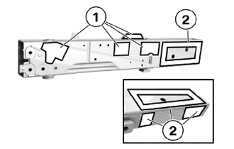
Prepare the front side member sub-assy (aluminium new part) in the areas (1) for bonding with the front fender apron sub-assy (aluminium used part).
Prepare the front side member sub-assy (aluminium new part) in the areas (2) for bonding.
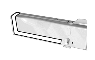
Prepare the front side member sub-assy aluminium new part in the marked areas for bonding.
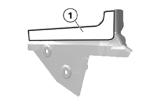
Prepare the front side member plate No.4 in the area (1) for steel bonding.
INSTALLATION
| Symbol Meaning | |
|---|---|

|
Plug Weld |
|
|
Adhesive |
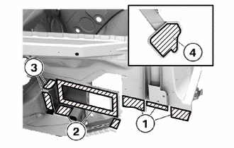
Apply adhesive to bonding surfaces (1) to (4).
- Adhesive:
K1 Bodywork Adhesive 195ml 08833-WA210
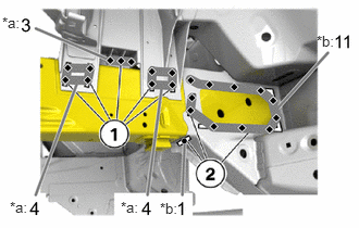
| *a | BLIND RIVET N2 HEMLOCK 815 |
| *b | BLIND RIVET N1 HEMLOCK 813 |
Install and secure front side member sub-assy.
Rivet the engine support in the areas (1) with the blind rivets N2.
- Expendable materials:
BLIND RIVET N2 HEMLOCK 815 φ 6.5 mm ; clamping range 4.8-6.8 mm 90118WA665
Rivet the engine support in the areas (2) with the blind rivets N1.
- Expendable materials:
BLIND RIVET N1 HEMLOCK 813 φ 6.5 mm ; clamping range 2.8-4.8 mm 90118WA664
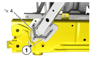
| *a | BLIND RIVET N1 HEMLOCK 813 |
Rivet the carrier support in the areas (1) with blind rivets N1.
- Expendable materials:
BLIND RIVET N1 HEMLOCK 813 φ 6.5 mm ; clamping range 2.8-4.8 mm 90118WA664
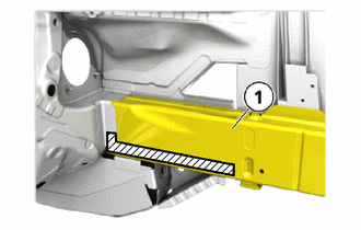
|
|
Adhesive |
Apply adhesive to the marked bonding surface of front side member sub-assy (1) and the front side member plate for the inner engine support.
- Adhesive:
K1 Bodywork Adhesive 195ml 08833-WA210
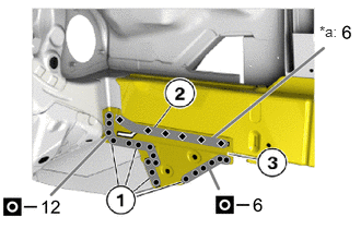
| *a | BLIND RIVET N1 HEMLOCK 813 |
Install the connecting plate (3) for the inner engine support and rivet in the area (2) with blind rivets N1.
- Expendable materials:
BLIND RIVET N1 HEMLOCK 813 φ 6.5 mm ; clamping range 2.8-4.8 mm 90118WA664
Weld the front side member plate No.4 (3) for the engine support inner in the areas (1).
| *a | BLIND RIVET N1 HEMLOCK 813 |
Rivet the front side member plate for the front top engine support and the engine support in the areas (1) and (2) with blind rivets N1.
In the area (2) , the rivet N1 is set through the hole in the front side member plate No.4 for the inner engine support.
- Expendable materials:
BLIND RIVET N1 HEMLOCK 813 φ 6.5 mm ; clamping range 2.8-4.8 mm 90118WA664
PREPARE THE ALUMINIUM SURFACE (NEW PART) FOR STRUCTURAL BONDING
Do not sand the bonding surfaces.
Remove coarse contamination from the bonding surfaces using solvent cleaner R2.
- Expendable materials:
Cleaner R2 500ml 08879-WA010
Clean the bonding surfaces using solvent cleaner R1.
- Expendable materials:
Cleaner R1 100ml, Bottle 08833-WA050
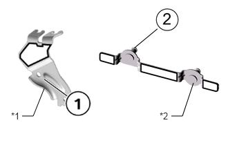
| *1 | STRUT BAR BRACKET REINFORCEMENT |
| *2 | DSC BRACKET |
Prepare the holder (1) for the strut bar bracket reinforcement in the marked area for bonding the new aluminium part.
Prepare the holder (2) for the DSC bracket in the marked area for bonding the new aluminium part.
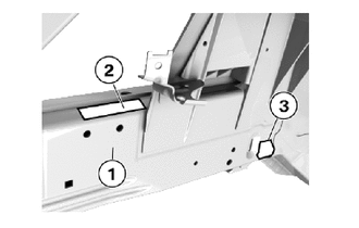
Prepare the front side member sub-assy (1) in the areas (2) and (3) for bonding aluminium on aluminium.
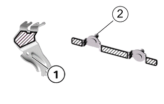
|
|
Adhesive |
Apply adhesive to the marked bonding surface on the holder for the strut bar bracket reinforcement (1).
Apply adhesive to the marked bonding surface of the holder for the DSC bracket (2).
- Adhesive:
K1 Bodywork Adhesive 195ml 08833-WA210
| *a | BLIND RIVET N1 HEMLOCK 813 |
Rivet the DSC bracket on front side member sub-assy with blind rivets N1.
- Expendable materials:
BLIND RIVET N1 HEMLOCK 813 φ 6.5 mm ; clamping range 2.8-4.8 mm 90118WA664
| *a | BLIND RIVET N1 HEMLOCK 813 |
Rivet the strut bar bracket reinforcement (1) on the front side member sub-assy (2) with blind rivets N1.
- Expendable materials:
BLIND RIVET N1 HEMLOCK 813 φ 6.5 mm ; clamping range 2.8-4.8 mm 90118WA664
INSTALL THE EMC SCREW (EMC = ELECTROMAGNETIC COMPATIBILITY)
After adhesive has fully hardened: Drill hole with diameter of 4.2 mm (0.17 in.).
- HINT:
-
The EMC screw can only be screwed in and sealed with sealant once the adhesive has fully hardened.
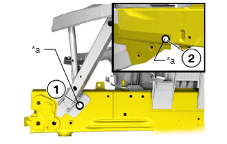
| *a | EMC SCREW |
Install an EMC screw in areas (1) and (2).
- Expendable materials:
EMC SCREW SF Plus, M5x15 90118WA666
Apply seam seal to the area (1) and (2).
- Expendable materials:
Seam Seal 310ml 08826-WA220
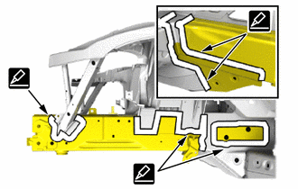
Apply seam seal to the rivets.
- Expendable materials:
Seam Seal 310ml 08826-WA220
After welding, apply body sealer and undercoating to the corresponding parts. (See the painting/coating)
After applying the top coat, apply anti-rust agent to the internal panel portion of the closed section structural weld points.