BM3650E
_01
Vehicle Exterior
_083396
BODY PANEL
_0402523
ROCKER OUTER PANEL
F
BODY PANEL ROCKER OUTER PANEL CUT AND JOIN REPLACEMENT SECTIONS
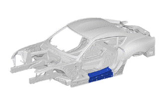
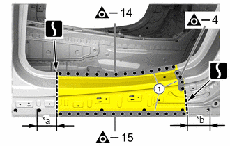
REMOVAL
| Symbol Meaning | |
|---|---|

|
Remove Weld Points |

|
Cut and Join Location |
a.
0.625,1.719 0.938,1.875
0.313,0.156
10
false
*a
2.927,1.708 3.24,1.865
0.313,0.156
10
false
*b
| *a | 97 mm (3.82 in.) from the front edge of the φ20 mm (0.79 in.) bore hole |
| *b | 124 mm (4.88 in.) from the rear edge of the φ20 mm (0.79 in.) bore hole |
Mark and perform the separating cuts to match the specified dimensions.
- NOTICE:
-
Thereby disconnect only the outer panel.
b.
Remove the weld points in areas (1).
INSTALLATION
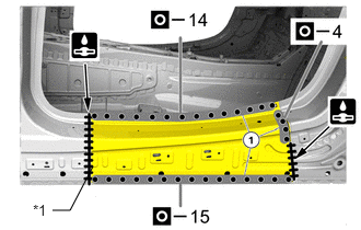
| Symbol Meaning | |
|---|---|

|
Plug Weld |

|
Butt Weld |
a.
0.5,2 0.667,2
0.667,2 0.885,1.583
false
0.313,1.917 0.625,2.073
0.313,0.156
10
false
*1
| *1 | SIDE PANEL SUB-ASSY OUTER |
Position the section of the side sill.
b.
Weld the side panel sub-assy outer in the areas (1).
c.
After welding, apply body sealer and undercoating to the corresponding parts. (See the painting/coating)
d.
After applying the top coat, apply anti-rust agent to the internal panel portion of the closed section structural weld points.