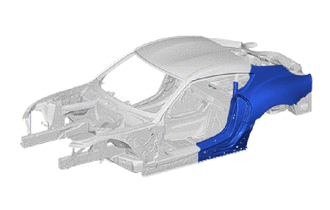
BODY PANEL QUARTER PANEL CUT AND JOIN REPLACEMENT SECTIONS
REMOVE THE HEMMING LOCATION
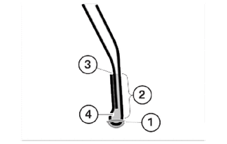
Grind down the flange edge (1) with an angle grinder with a roughing wheel.
Heat the adhesive flange (2) with a hot air blower.
- NOTICE:
-
Do not exceed the maximum object temperature of 250°C.
Use pliers or a chisel to peel off the components.
- NOTICE:
-
Do not damage adjacent components.
Remove the sealant in the area (3).
Remove adhesive residue (4) from the adhesive flange.
REMOVAL
| Symbol Meaning | |
|---|---|

|
Remove Weld Points |

|
Cut and Join Location |
Mark and perform the separating cuts to much the specified dimensions.
- NOTICE:
-
Disconnect only the outer panel.
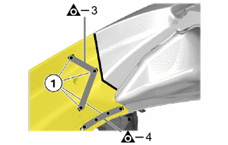
Remove the welding points in areas (1).
Remove the hemming location in area (2).
Remove side panel sub-assy outer from the foamed sealing material (3).
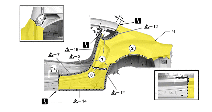
| *1 | SIDE PANEL SUB-ASSY OUTER | - | - |
| *a | 140 mm (5.51 in.) from the front edge of the bore hole in the door sill cover strip | *b | 65 mm (2.56 in.) from the upper edge of the hole |
| *c | 130 mm (5.12 in.) from the corner of the side frame | - | - |

|
Foamed Sealing Material | - | - |
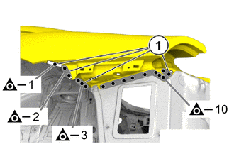
Remove the welding points in areas (1).
Remove the welding points in areas (1).
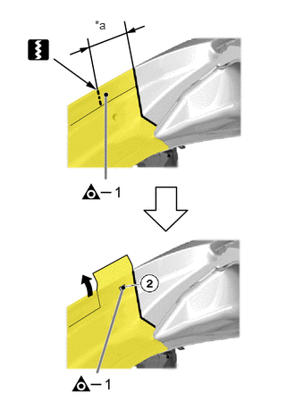
| *a | 70 mm (2.76 in.) |
Remove the welding points in areas (2).
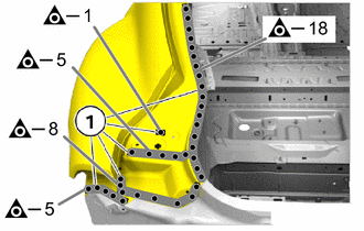
Remove the welding points in areas (1).
Prepare new part
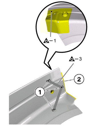
Remove the welding points in areas (1).
Remove a section of the (2).
INSTALL THE FOAMED SEALING MATERIAL
- HINT:
- ·
Schematic diagram is for example purposes.
·Some parts may differ in certain details.
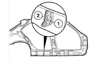
Clean the contact surface (1) with the cleaner R2.
- Expendable materials:
Cleaner R2 500ml 08879-WA010
On the contact surface (1), apply an approximately 15 mm bead (2) of brushable seam seal.
If necessary apply a slightly thinner bead of brushable seam seal on each side, to prevent the sealant from running.
- Expendable materials:
Brushable Seam Seal 310ml 08826-WA230
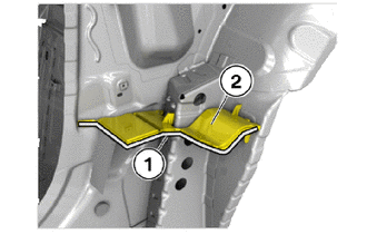
Remove existing foamed sealing material in the repair area with cavity wax remover.
- Expendable materials:
Cavity Wax Remover 500ml, Spray bottle 08830-WA010 Cleaner R2 500ml 08879-WA010
Apply brushable seam seal in the area (1) to the foamed sealing material (2).
- Expendable materials:
Brushable Seam Seal 310ml 08826-WA230
INSTALLATION
| Symbol Meaning | |
|---|---|

|
Plug Weld |

|
Butt Weld |
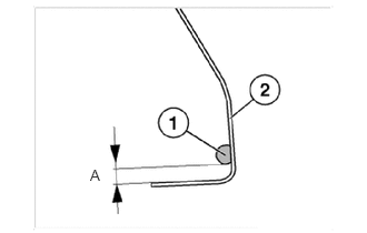
| A | 5 mm (0.20 in.) |
Apply adhesive (1) to the new part in the area (2) of the wheel arch.
- Adhesive:
K1 Bodywork Adhesive 195ml 08833-WA210
Apply adhesive (1) on the inside of the side panel at a distance (A).
Weld the side panel sub-assy outer in the areas (1).
- NOTICE:
-
When using welds to attach panels that were previously attached using adhesive, it must be welded by plug welding (MAG welding), no adhesive should be applied. The number of plug welds (MAG welding) must be doubled compared to the original welding points on the adhesive applied areas.
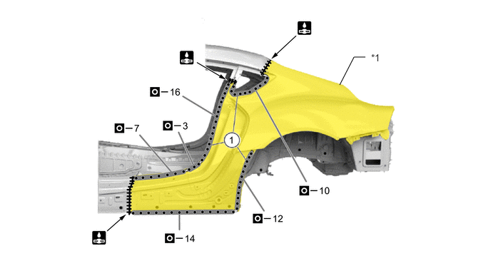
| *1 | SIDE PANEL SUB-ASSY OUTER | - | - |
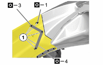
Weld the side panel sub-assy outer in the areas (1).
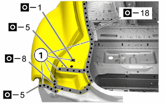
Weld the side panel sub-assy outer in the areas (1).
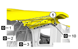
Weld the side panel sub-assy outer in the areas (1).
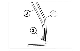
Apply adhesive (2) above the side panel (1) on the outer wheel arch section (3).
- Adhesive:
K1 Bodywork Adhesive 195ml 08833-WA210
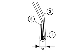
| *a | 5 mm (0.20 in.) |
Flange the edge of wheel arch (3) of the side panel (2) flush to the outer wheel arch section.
- HINT:
-
Do not create sharp edges when flanging as otherwise the flange edge may begin to tear.
Fully fill flange edge (1) with adhesive.
- Adhesive:
K1 Bodywork Adhesive 195ml 08833-WA210
Apply Seam Seal to the area of the edge of wheel arch (3).
- Expendable materials:
Seam Seal 310ml 08826-WA220
After welding, apply body sealer and undercoating to the corresponding parts. (See the painting/coating)
After applying the top coat, apply anti-rust agent to the internal panel portion of the closed section structural weld points.