INTRODUCTION ABOUT THIS VEHICLE STRUCTURAL OUTLINE
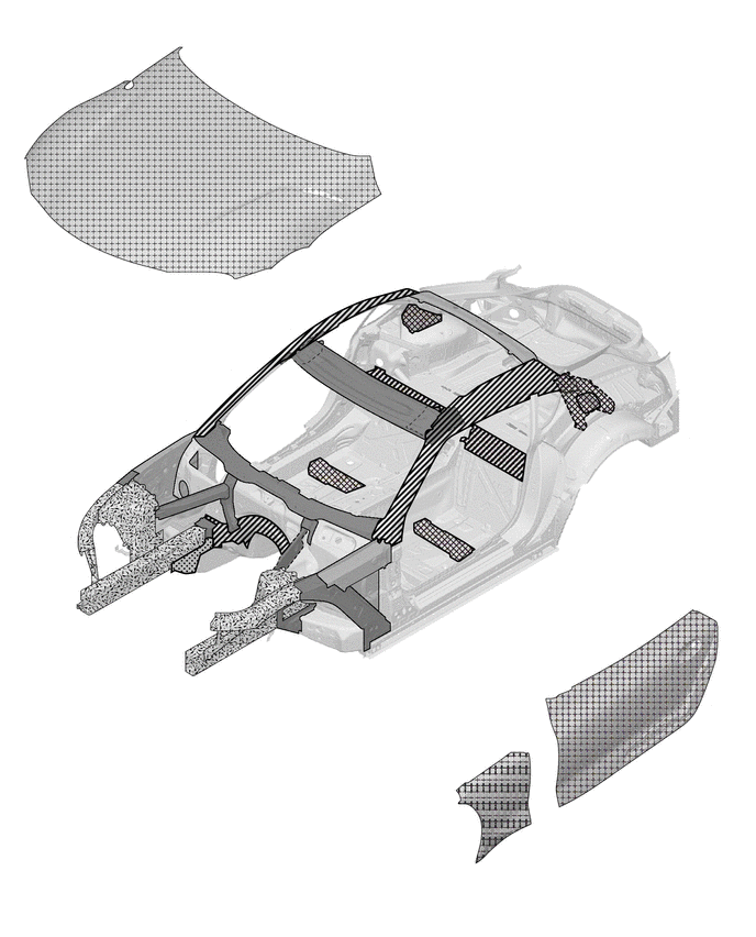

|
1180 MPa Ultra High Strength Steel | 
|
980 MPa Ultra High Strength Steel |

|
780 MPa Ultra High Strength Steel | 
|
440 MPa High Strength Steel |

|
340 MPa High Strength Steel | 
|
Aluminum |

|
Aluminum | - | - |
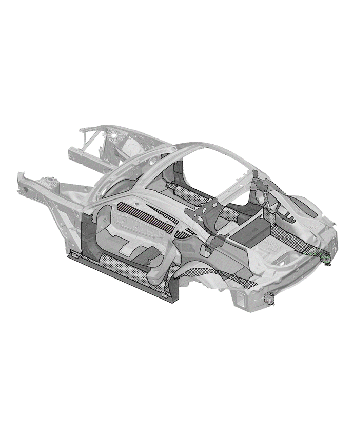
|
|
1180 MPa Ultra High Strength Steel |
|
980 MPa Ultra High Strength Steel |
|
|
780 MPa Ultra High Strength Steel |
|
440 MPa High Strength Steel |

|
390 MPa High Strength Steel |
|
340 MPa High Strength Steel |
|
|
Aluminum | - | - |
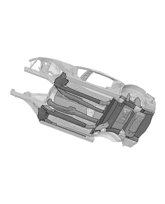
|
|
1180 MPa Ultra High Strength Steel |
|
980 MPa Ultra High Strength Steel |
|
|
780 MPa Ultra High Strength Steel |
|
440 MPa High Strength Steel |
|
|
390 MPa High Strength Steel |
|
340 MPa High Strength Steel |
PROHIBITION OF MODIFYING ALUMINUM FRAME PARTS
Aluminum frame parts must not be repaired by the frame aligning machine. Replace the parts when aligning.
Aluminum frame parts must be replaced in case that crack or deformation is found by visual inspection or measurement.Insert blind rivet nuts or bolts and tighten down with rivet tool .
REMOVING SELF-TAPPING SCREWS
- HINT:
- ·
Schematic diagram is for example purposes.
·Some parts may differ in certain details.
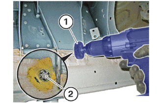
Remove the sealant with a wire brush attachment (1).
Completely remove the sealant from the screw head (2).
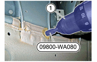
Vertically position the battery-powered drill (1) using special tool 09800-WA080 on the self-tapping screw and release the self-tapping screw.
TRANSFERRING HOLE PATTERN
- HINT:
- ·
Schematic diagram is for example purposes.
·Some parts may differ in certain details.
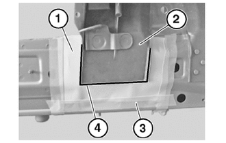
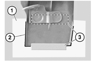
Insert a template (paper template) (1) between the new part (2) and the body and secure it with adhesive tape (3).
Transfer the outline (4) of the new part to the template.
Remove the new part (2).
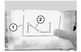
Use your thumbs to press down on the positions of the bore holes (2) and transfer them to the template.
The outline of the new part (1) provides better orientation.
Remove the template.
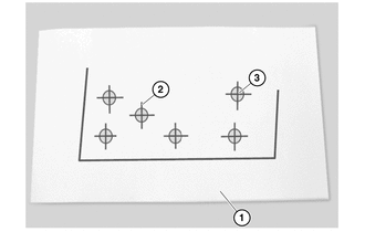
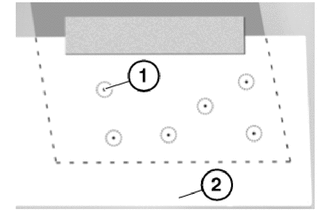
Place the template (1) onto a flat surface.
Mark the centre points of the bore holes with X (2).
Use a sharp object to punch through the paper to transfer the centre points (3) of the bore holes.
Align the template (1) according to the outlines (2) on the inside of the new part.
Secure the template (1) with adhesive tapes (3).
Turn the new part around.
- HINT:
-
The X marks must not be visible from this view.
Set punch marks at the pressed through centre points (1). Provide counter support directly below the punch marks for punching.
Remove the template (2).
At the punch marks (1) drill bore holes with a diameter of approximately 3 mm (0.12 in.).
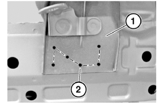
Position the new part (1) on the vehicle.
Drill out the bore holes (2) to a diameter of 6.8 mm (0.27 in.).
FIX BOLTS ON THE NEW PART
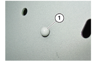
Single ball/double ball (version 1):
Grind off any residues of the single ball (1), ifapplicable.
Drill hole with diameter 7 mm (0.28 in.).
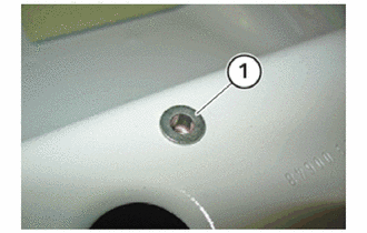
Set blind rivet nut (1).
Screw in single ball with thread until a height of 5 mm (0.20 in.) (double ball 10 mm (0.39 in.)) is reached.
Single ball/double ball (version 2):
Grind off any residues of the single ball (1), if applicable.
Clean area with solvent cleaner R1.
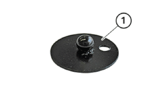
Clean bonding surface of repair element singleball (1) with solvent cleaner R1.
Bond repair element optionally with adhesive K1, K5 or window pane adhesive at the same position.
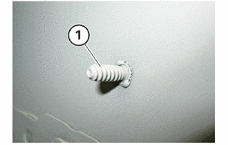
Coarse threaded bolt (version 1):
Grind off any residues of the coarse threaded bolt (1), if applicable.
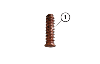
Spot weld coarse threaded bolt to sameposition.
Coarse threaded bolt (version 2):
Grind off any residues of the coarse threadedbolt (1), if applicable.
Drill hole with diameter 7 mm (0.28 in.).
Set blind rivet coarse threaded bolt usingriveting pliers.
REPAIR SOLUTION FOR STRAIGHT SHANK/HEXAGON RIVET NUT
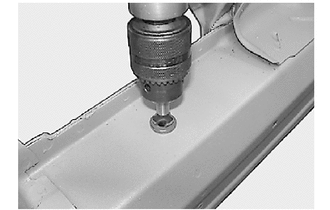
Carefully spot-drill rivet head with a larger drillbit/countersink
- HINT:
-
To prevent the material from tapering, donot drill out the rivet head.
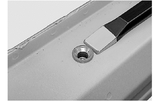
Knock rivet head away with a chisel.
- HINT:
-
Avoid paint damage
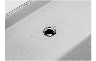
Punch through rivet shank into cavity, remove if necessary
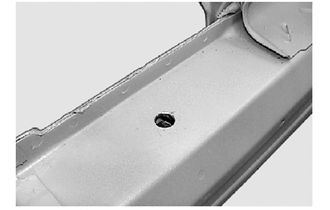
Clean component, eliminate paint damage if necessary
If the rivet shank can be removed.
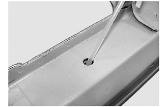
Preserving cavity
- HINT:
- ·
To avoid corrosion, stop chips/swarf by means of cavity preservation.
·Follow notes on corrosion protection.
If the rivet shank cannot be removed.
Stop rivet shank by means of specific foaming.
- NOTICE:
- ·
Danger of injury!
·Observe notes on cavity foam.
- HINT:
- ·
To avoid corrosion and rattling noises, stopchips/swarf and rivet nut shank with cavity foam.
·Remove foam remnants with isohexane (benzine).
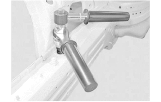
Set rivet nut with 09000-WA040.
- HINT:
-
Fit rivet nut as quickly as possibly, ideally before the cavity foam hardens.
Hexagon/straight shank rivet nut (up to thread M12) with 09000-WA040
STANDARD ELEMENTS FOR BODY REPAIR
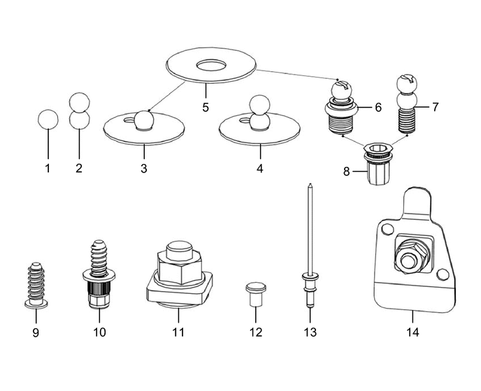
| No. | Part Name | Details | Material | Part Number |
|---|---|---|---|---|
| 1 | SINGLE BALL, SUITABLE FOR WELDING | - | Steel | 90118-WA668 |
| 2 | DOUBLE BALL, SUITABLE FOR WELDING | - | Steel | 90118-WA758 |
| 3 | SINGLE BALL WITH ADHESIVE FLANGE | - | Steel | 90118-WA669 |
| 4 | DOUBLE BALL WITH ADHESIVE FLANGE | - | Steel | 90118-WA755 |
| 5 | SHIM | - | Plastic | 90118-WA671 |
| 6 | SIMPLE BALL WITH THREADED BOLT | - | Steel | 90118-WA670 |
| 7 | DOUBLE BALL WITH THREADED BOLT | - | Steel | 90118-WA756 |
| 8 | BLIND RIVET NUT, COUNTERSUNK HEAD | M5 L=15 mm | Steel | 90118-WA679 |
| 8 | BLIND RIVET NUT, COUNTERSUNK HEAD | M5 L=11.6 mm | Steel | 90118-WA672 |
| 8 | BLIND RIVET NUT, COUNTERSUNK HEAD | M5 L=20 mm | Steel | 90118-WA676 |
| 9 | COARSE-THREAD STUD | L=14.2 mm | Steel | 90118-WA674 |
| 9 | COARSE-THREAD STUD | L=15.5 mm | Aluminum | 90118-WA677 |
| 10 | RIVET PIN WOTJ COARSE THREAD | L=22.5 mm | Steel | 90118-WA675 |
| 10 | RIVET PIN WOTJ COARSE THREAD | L=25 mm | Steel | 90118-WA678 |
| 11 | EARTH PIN | - | Steel | 90118-WA157 |
| 12 | T-WELDING STUD | - | Steel | 90118-WA682 |
| 13 | REPAIR RIVET FOR T-BOLT | - | Aluminum | 90118-WA757 |
| 14 | GROUND PIN 48V | - | Steel | 90118-WA759 |
SETTING BLIND RIVET NUTS AND BOLTS
Studs welded as standard are always replaced by blind rivet bolts.
Drill holes (0.2 mm (0.01 in.) larger than the outside diameter of the blind rivet nuts or blind rivet bolts).
Blind rivet nuts and studs must have a special coating for anti-corrosion purposes.
USE THE BLIND RIVET NUTS AND BOLTS SUPPLIED IN THE CASE OF THE MANUAL RIVETING TOOL FOR STEELONLY!
It will no longer be possible to set a blind rivet nut if the drilled hole is too big. In this event, seta clip nut. This nut tightens itself automaticallywhen screwed to the component.
Insert blind rivet nuts or bolts and tighten down with rivet tool .
Seal blind rivet nuts and blind rivet bolts with sealantD1 (risk of corrosion).
GENERAL NOTES FOR EMC SCREWS
EMC screws (EMC = electromagnetic compatibility) are used with the bonding/riveting technology repair method to restore the ground connection between the individual components.
The EMC screws are responsible for the same task as the standard connections, that guarantee the ground connection between the individual components in standard production.
The punch or blind rivets used in the repair do not guarantee a permanent ground connection between the individual components.
The EMC screws ensure the operational reliability and safety of the electrical or electronic components following repairs!
Install the number of EMC screws specified in the vehicle-specific repair instructions.
INSTALL THE EMC SCREW (EMC = ELECTROMAGNETIC COMPATIBILITY)
After adhesive has fully hardened: Drill hole with diameter of 4.2 mm (0.17 in.).
- HINT:
-
The EMC screw can only be screwed in and sealed with sealant once the adhesive has fully hardened.
MATERIAL PROCESSING
The following operations describe passivation:
Remove oxide layer from the bonding surface using a stainless steel wire brush or special sandpaper. The desired adhesion between the adhesive and component is established in this way.
Clean bonding surface using a cleaning agent (workshop designation R1) and leave no residue. Allow to dry completely.
Flame coat bonding surface using special burner and the primer (workshop designation P2). Here the bonding surface is slowly worn down with the burner flame. It is important to avoid flame treatment with the blue part of the flame.
Apply a second primer (workshop designation P1) using a clean brush to the bonding surface. This must be done shortly after the flame treatment on the bonding surface when it is still warm (approx. 50 °C).
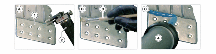
| A | Flame coating | B | Apply primer |
| C | Apply adhesive | - | - |
| 1 | Aluminium component | 2 | Burner |
| 3 | Brush | 4 | Glue cartridge |