BM3650E
_01
Vehicle Exterior
_083398
BODY DIMENSIONS
_0402540
ENGINE COMPARTMENT
F
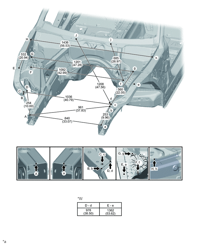
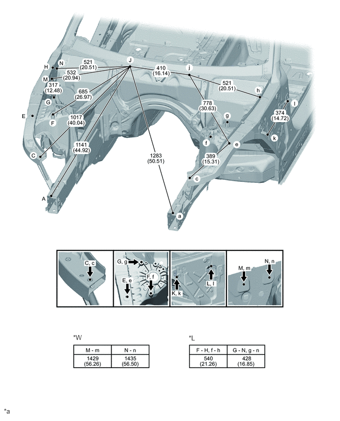
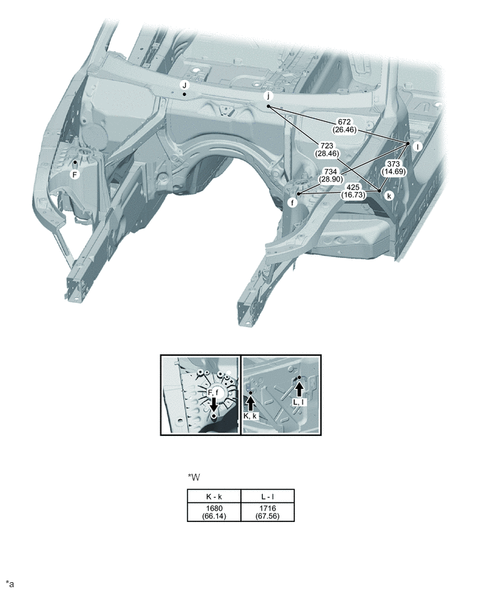
BODY DIMENSIONS ENGINE COMPARTMENT POINT-TO-POINT DISTANCE
- HINT:
- ·
In cases in which only one dimension is given, left and right are symmetrical.
·For symbols, capital letters indicate right side of vehicle, small letters indicate left side of vehicle (seen from rear).
| Symbol | Name | Hole Diameter
mm (in.) |
|---|---|---|
| A, a | Corner fold of outer engine support | - |
| B, b | Corner of outer front upper wheel arch carrier support | - |
| C, c | Rivet nut of upper front wheel arch carrier support | M10 (0.39) |
| D. d | Corner of support of inner front upper carrier support | - |
| E, e | Hole for upper wheel arch carrier support | φ20 (0.79) |
| F, f | Hole for front spring support | φ9 (0.35) |
| G, g | Screw point of dome-bulkhead-stiffening plate on outer wheel arch section | M10 (0.39) |
| H, h | Corner of tab on front carrier support | - |
| J, j | Inner screw point of dome-bulkhead-stiffening plate on the upper section of bulkhead cross member | M8 (0.31) |
| K, k | Screw point of front - front side panel holder | 10X10
(0.39x0.39) |
| L, l | Screw point of rear - front side panel holder | φ10 (0.39) |
| M, m | Screw point of front bonnet hinge | M8 (0.31) |
| N, n | Screw point of rear bonnet hinge | M8 (0.31) |
0.094,8.594 0.406,8.75
0.313,0.156
10
false
*a
2.792,7.052 3.104,7.208
0.313,0.156
10
false
*W
| *a | mm
(in.) |
- | - |
| *W | Width distance | - | - |
0.083,8.583 0.417,8.75
0.333,0.167
10
false
*a
1.542,7.031 1.854,7.188
0.313,0.156
10
false
*W
3.979,7.042 4.292,7.198
0.313,0.156
10
false
*L
| *a | mm
(in.) |
- | - |
| *W | Width distance | *L | Length distance |
0.083,8.594 0.396,8.75
0.313,0.156
10
false
*a
2.792,7.01 3.104,7.167
0.313,0.156
10
false
*W
| *a | mm
(in.) |
- | - |
| *W | Width distance | - | - |