B48 ENGINE MECHANICAL ENGINE UNIT DETAILS CONTINUOUSLY VARIABLE VALVE LIFT CONTROLLER
CONSTRUCTION
A servomotor (camshaft timing oil control valve assembly) located on the intake valve side performs the fully variable valve lift control via the eccentric shaft (No. 3 camshaft sub-assembly) and intermediate lever (tension arm sub-assembly).
The ECM controls the servomotor (camshaft timing oil control valve assembly) on the cylinder head sub-assembly to vary the angle of the eccentric shaft (No. 3 camshaft sub-assembly) by driving the worm gear.
Engine oil circulates around the servomotor (camshaft timing oil control valve assembly), and the oil spray nozzle lubricates the eccentric shaft (No. 3 camshaft sub-assembly) and worm gear.
The side of the intermediate lever (tension arm sub-assembly) is connected to and oscillates with the eccentric shaft (No. 3 camshaft sub-assembly).
The drive force transmitted via the intake camshaft sub-assembly presses down the No. 1 valve rocker arm sub-assembly via the intermediate lever (tension arm sub-assembly).
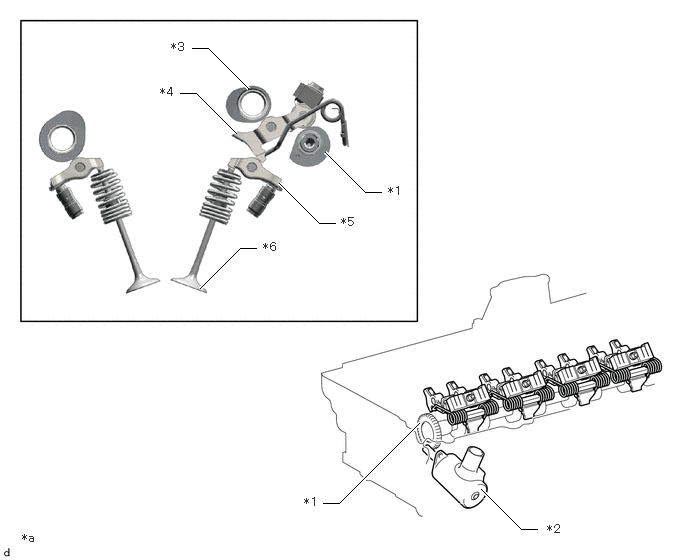
| *1 | Eccentric Shaft (No. 3 Camshaft Sub-assembly) | *2 | Servomotor (Camshaft Timing Oil Control Valve Assembly) |
| *3 | Intake Camshaft Sub-assembly | *4 | Intermediate Lever (Tension Arm Sub-assembly) |
| *5 | No. 1 Valve Rocker Arm Sub-assembly | *6 | Valve |
| *a | The illustrations shown are examples only. | - | - |
OPERATION
In response to the drive force of the worm gear on the servomotor (camshaft timing oil control valve assembly), the angle of the eccentric shaft (No. 3 camshaft sub-assembly) is varied.
In response to the changing angle of the eccentric shaft (No. 3 camshaft sub-assembly), the fulcrum of oscillation of the intermediate lever (tension arm sub-assembly) varies.
By displacing the fulcrum of rotation of the intermediate lever (tension arm sub-assembly), the location and angle of the drive force transmitted from the camshaft to the No. 1 valve rocker arm sub-assembly varies.
The changes to transmission point and angle of drive force on the No. 1 valve rocker arm sub-assembly vary the reciprocating motion of the valves, with an associated variation in valve lift amount.