B58 EMISSION CONTROL EMISSION CONTROL SYSTEM CONTROL EVAPORATIVE EMISSION CONTROL
FUNCTION
Canister purge control suppresses the release of fuel vapor from the fuel tank.
The fuel tank breather valve is a solenoid valve that is controlled via a Pulse Width Modulation (PWM) signal from the ECM, which controls the purge quantity sent to the engine.
When the engine is stopped, the fuel tank breather valve closes to block off the purge line that leads from the fuel filter assembly to the intake manifold side, thus preventing the flow of fuel vapor into the engine.
Air ventilation proceeds from the fuel tank to the outside air via the fuel filter assembly to which the fuel vapor adsorbs.
The tank leak diagnosis using Natural Vacuum Leak Detection (NVLD) takes place in the rest state after the switching off the engine. Due to the temperature difference between day and night, the fuel tank and the fuel contained therein cool down uniformly and a vacuum arises. The diaphragm valve closes as a result of the pressure difference between the fuel tank ventilation system and the ambient air. The pressure switch is actuated by the diaphragm valve from a predefined vacuum in the fuel tank. (Models with fuel temperature sensor)
OPERATING CONDITION
The tank leak diagnosis is started under the following conditions. (Models with fuel temperature sensor)
| Typical Enabling Conditions | ·
Cold start ·
Ambient temperature greater than 4.5°C (40.1°F) ·
Cooling of more than 8°C (46.4°F) over longer than 1 hour ·
Less than 2500 m (8202 ft.) above sea level ·
Fuel tank breather valve closed ·
Terminal status after-run or vehicle gone to sleep ·
Battery voltage between 11 V to 16 V ·
Pressure difference for ambient pressure between engine OFF and engine start less than 6 hPa (6 mbar) |
OPERATION
Tank ventilation
The fuel tank breather valve controls the regeneration of the fuel filter assembly by means of scavenging air. The scavenging air sucked in by the fuel filter assembly accumulates hydrocarbons (HC) depending on the fuel filter assembly load. The scavenging air is subsequently fed to the engine for combustion.
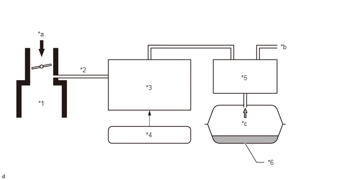
| *1 | Intake Manifold | *2 | Purge Line |
| *3 | Fuel Tank Breather Valve | *4 | ECM |
| *5 | Fuel Filter Assembly (Models with Fuel Temperature Sensor)/ No. 1 Charcoal Canister Filter (Models without Fuel Temperature Sensor) | *6 | Fuel Tank |
| *a | Intake Air | *b | Atmosphere |
| *c | Fuel Vapor | - | - |
Natural Vacuum Leak Detection (NVLD) (Models with fuel temperature sensor)
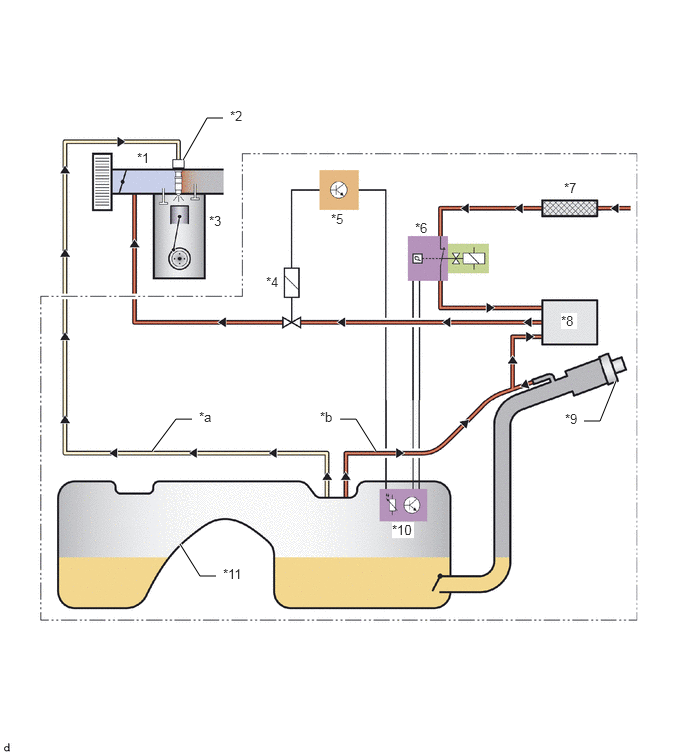
| *1 | Intake Manifold | *2 | Fuel Injector Assembly |
| *3 | Engine | *4 | Fuel Tank Breather Valve |
| *5 | ECM | *6 | Pressure Switch |
| *7 | Dust Filter | *8 | Fuel Filter Assembly |
| *9 | Fuel Tank Cap Assembly | *10 | Fuel Temperature Sensor |
| *11 | Fuel Tank | - | - |
| *a | Flow of Fuel | *b | Fuel Vapor |
Rest state
Atmospheric pressure exerts its force on the top side of the diaphragm and poppet valve. The inner pressure is not defined here.
The pressure switch is opened. The poppet valve forms a perfect seal.
There is no active air circulation between the fuel tank and surrounding area.
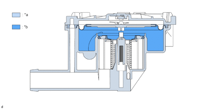
| *a | Partial Vacuum | *b | Atmospheric Pressure |
Pressure switch closes
A vacuum in the tank ventilation system raises the top rubber diaphragm against the pressure switch.
The pressure switch closes.
There is no active air circulation between the fuel tank and surrounding area.
The bottom poppet valve is pressed against the seal by the spring.
The tank ventilation system is not leaking.
- HINT:
-
Vacuum approx. 2.5 hPa (2.5 mbar)
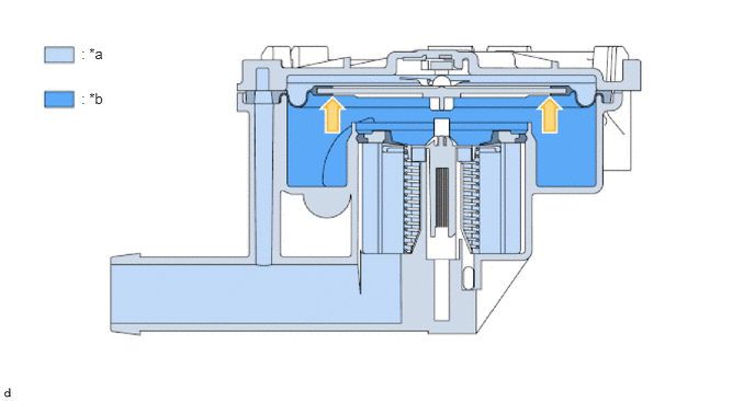
| *a | Partial Vacuum | *b | Atmospheric Pressure |
Scavenging air mode
An increased vacuum (scavenging air mode) in the tank ventilation system causes the poppet valve to open slightly.
Scavenging air flows from the fresh air filter into the fuel filter assembly.
The vacuum present continues to lift the diaphragm against the pressure switch.
The pressure switch remains closed.
The tank ventilation system is not leaking.
- HINT:
-
Vacuum greater than 8 hPa (8 mbar)
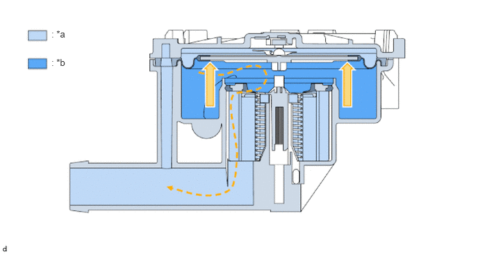
| *a | Partial Vacuum | *b | Atmospheric Pressure |
Excess pressure
If the pressure in the tank ventilation system is somewhat greater than the atmospheric pressure, the diaphragm presses down on the poppet valve.
The poppet valve opens. Gas flows out of the tank ventilation system through the fresh air filter and into the open.
The pressure switch is opened.
- HINT:
-
Pressure greater than 2 hPa (2 mbar)
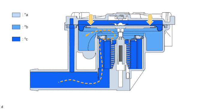
| *a | Partial Vacuum | *b | Atmospheric Pressure |
| *c | Excess Pressure | - | - |
Refueling
The system pressure increases dramatically while refueling. This causes the top diaphragm to lower. The top diaphragm simultaneously presses down strongly on the poppet valve underneath.
Gas flows out of the tank ventilation system through the fresh air filter and into the open.
The pressure switch is opened.
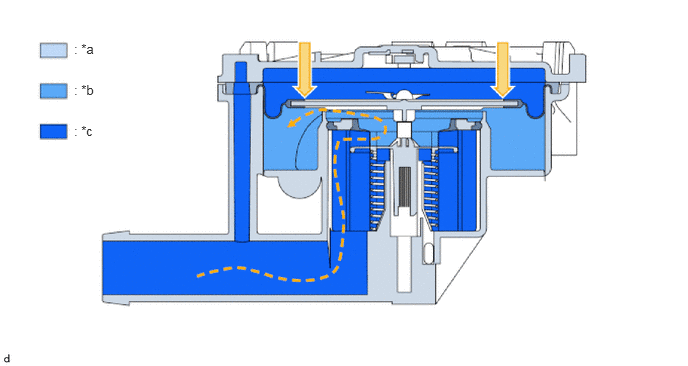
| *a | Partial Vacuum | *b | Atmospheric Pressure |
| *c | Excess Pressure | - | - |