B58 EMISSION CONTROL EMISSION CONTROL SYSTEM DETAILS BLOWBY GAS VENTILATION CONTROL
OPERATION
A 2-stage mechanism for recirculation of blowby gas has been provided. Blowby gas flows through the following different pathways depending on load condition.
When driving at low load:
When driving at low load, the vacuum level in the intake manifold is high. Due to this vacuum, the blowby gas passes through the oil trap via the check valve of the intake manifold, and is drawn into the intake manifold from the crankcase. The oil contained within the blowby gas is separated by the oil trap.
Compared to the flow volume of the generated blowby gas, the flow volume from the air bleed valve of the crank housing is much greater, and due to the airtightness of the crankcase, a vacuum develops within the crankcase and its connected passageways.
Fresh air flows into the circuit through the bypass built into the check valve of the fresh air pipe. The vacuum inside the crankcase is controlled by this portion of outside air.
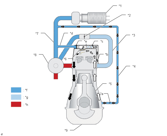
| *1 | Air Cleaner Assembly
·
Air Cleaner Filter Element Sub-assembly |
*2 | Throttle Body with Motor Assembly |
| *3 | Intake Manifold | *4 | Purge Air Line |
| *5 | Crankcase | *6 | Oil Trap |
| *7 | Air Cleaner Hose Assembly | *8 | Turbocharger Sub-assembly |
| *9 | Oil Pan Sub-assembly | - | - |
| *a | Check Valve (from Bypass) | *b | Flow Path (within Cylinder Head and Cylinder Head Cover) |
| *c | Check Valve (to Intake Manifold) | *d | Flow Path (to Air Cleaner Hose Assembly) |
| *e | Check Valve (to Air Cleaner Hose Assembly) | *f | Atmosphere Pressure |
| *g | Vacuum | *h | Exhaust Gas |

|
Oil after Separation | 
|
Blowby Gas |

|
Flow of Fresh Air | - | - |
When driving at high load
When driving at high load, there is no vacuum inside the intake manifold, and in fact the pressure in some parts is higher than the outside air pressure, so the blowby gas cannot be directly recirculated into the intake manifold.
The pressure difference causes the check valve (to intake manifold), set as a flow path to the intake manifold, to close. Consequently, the check valve (to air cleaner hose assembly), set as a flow path to the air cleaner hose assembly, opens and the blowby gas is sent to the air cleaner hose assembly via the oil trap. The oil contained within the blowby gas is separated by the oil trap.
The blowby gas merges with fresh air before the turbocharger sub-assembly, and is supplied to the engine together with the intake air from outside.
In this condition, the pressure inside the crankcase becomes approximately the same as the atmospheric pressure.
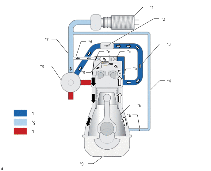
| *1 | Air Cleaner Assembly
·
Air Cleaner Filter Element Sub-assembly |
*2 | Throttle Body with Motor Assembly |
| *3 | Intake Manifold | *4 | Purge Air Line |
| *5 | Crankcase | *6 | Oil Trap |
| *7 | Air Cleaner Hose Assembly | *8 | Turbocharger Sub-assembly |
| *9 | Oil Pan Sub-assembly | - | - |
| *a | Check Valve (from Bypass) | *b | Flow Path (within Cylinder Head and Cylinder Head Cover) |
| *c | Check Valve (to Intake Manifold) | *d | Flow Path (to Air Cleaner Hose Assembly) |
| *e | Check Valve (to Air Cleaner Hose Assembly) | *f | Boost Pressure |
| *g | Vacuum | *h | Exhaust Gas |
|
|
Oil after Separation |
|
Blowby Gas |