Home › Engine / Hybrid System › B58 (COOLING) › COOLING SYSTEM
NM3650E _51 Engine / Hybrid System _082606 B58 COOLING _0398577 COOLING SYSTEM CO CONTROL F

B58 COOLING  COOLING SYSTEM  CONTROL  VARIABLE COOLING CONTROL  


FEATURES


a.

A variable cooling system has been adopted via a heat management module (water valve) which uses a rotary valve and an integrated electric split cooling valve, providing appropriate cooling for various driving conditions.

i.

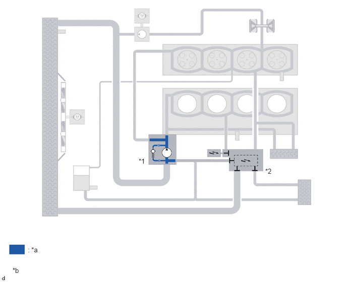
Cold start

·

The rotary valve inside the heat management module (water valve) closes, and coolant is circulated within the water inlet housing with water pump sub-assembly.
W143000C01
5.479,3.458 5.948,3.615 0.469,0.156 10 false *2 2.865,3.25 3.333,3.406 0.469,0.156 10 false *1 0.573,5.083 0.885,5.24 0.313,0.156 10 false : *a 0.26,5.51 0.573,5.667 0.313,0.156 10 false *b
*1 Water Inlet Housing with Water Pump Sub-assembly *2 Heat Management Module (Water Valve)
*a Coolant *b The illustrations shown are examples only.


ii.

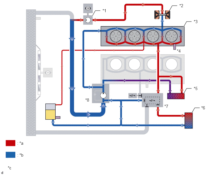
Warm up

·

The cylinder head, turbocharger, etc. are cooled according to the opening of the rotary valve of the heat management module (water valve). The coolant pathway to the cylinder block is closed by the electric split cooling valve.
W143001C01
6.125,3.115 6.219,2.948 6.219,2.948 6.385,2.948 true 6.396,3.76 6.49,3.594 6.49,3.594 6.656,3.594 true 6.125,0.885 6.219,0.719 6.219,0.719 6.385,0.719 true 5.646,0.354 5.74,0.188 5.74,0.188 5.906,0.188 true 3.083,0.521 3.177,0.354 3.177,0.354 3.344,0.354 true 3.417,0.271 3.729,0.427 0.313,0.156 10 false *1 5.979,0.104 6.292,0.26 0.313,0.156 10 false *2 6.458,0.635 6.771,0.792 0.313,0.156 10 false *3 5.896,1.615 6.208,1.771 0.313,0.156 10 false *4 6.458,2.865 6.771,3.021 0.313,0.156 10 false *5 6.708,3.51 7.021,3.667 0.313,0.156 10 false *6 5.479,3.458 5.948,3.615 0.469,0.156 10 false *7 2.844,3.25 3.313,3.406 0.469,0.156 10 false *8 0.573,4.688 0.885,4.844 0.313,0.156 10 false : *a 0.573,5.083 0.885,5.24 0.313,0.156 10 false : *b 0.26,5.51 0.573,5.667 0.313,0.156 10 false *c
*1 Water Pump Assembly (for Turbocharger) *2 Turbocharger
*3 Cylinder Head Sub-assembly *4 Engine Coolant Temperature Sensor (for Engine)
*5 Oil Cooler Assembly *6 Heater Radiator Unit Sub-assembly
*7 Heat Management Module (Water Valve)
·

Electric Split Cooling Valve


*8 Water Inlet Housing with Water Pump Sub-assembly
*a High Temperature Coolant *b Low Temperature Coolant
*c The illustrations shown are examples only. - -


iii.

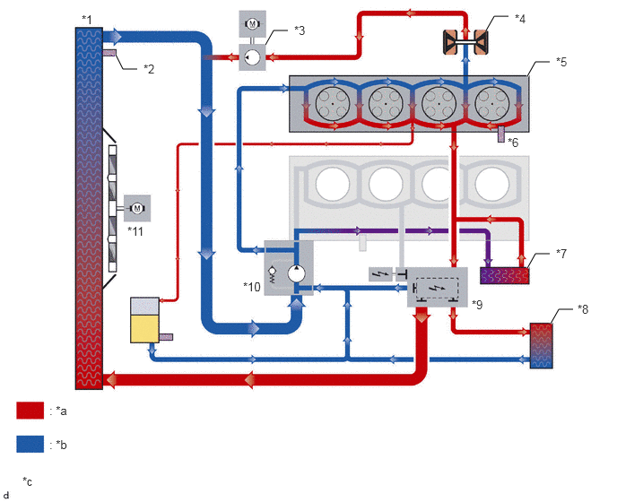
Engine operating temperature

·

Coolant flow volume through the various coolant pathways is varied according to engine load.
W143002C01
6.125,3.115 6.219,2.948 6.219,2.948 6.385,2.948 true 6.396,3.76 6.49,3.594 6.49,3.594 6.656,3.594 true 1.344,0.635 1.427,0.802 1.427,0.802 1.594,0.802 true 6.125,0.885 6.219,0.719 6.219,0.719 6.385,0.719 true 5.646,0.354 5.74,0.188 5.74,0.188 5.906,0.188 true 3.083,0.521 3.177,0.354 3.177,0.354 3.344,0.354 true 0.948,0.146 1.26,0.302 0.313,0.156 10 false *1 1.667,0.719 1.979,0.875 0.313,0.156 10 false *2 3.417,0.271 3.729,0.427 0.313,0.156 10 false *3 5.979,0.135 6.292,0.292 0.313,0.156 10 false *4 6.458,0.635 6.771,0.792 0.313,0.156 10 false *5 5.896,1.573 6.208,1.729 0.313,0.156 10 false *6 6.458,2.865 6.771,3.021 0.313,0.156 10 false *7 6.708,3.51 7.021,3.667 0.313,0.156 10 false *8 5.479,3.458 5.948,3.615 0.469,0.156 10 false *9 2.823,3.25 3.292,3.406 0.469,0.156 10 false *10 0.573,4.688 0.885,4.844 0.313,0.156 10 false : *a 0.573,5.083 0.885,5.24 0.313,0.156 10 false : *b 0.26,5.51 0.573,5.667 0.313,0.156 10 false *c 1.479,2.604 1.948,2.76 0.469,0.156 10 false *11
*1 Radiator Assembly *2 Engine Coolant Temperature Sensor (for Radiator)
*3 Water Pump Assembly (for Turbocharger) *4 Turbocharger
*5 Cylinder Head Sub-assembly *6 Engine Coolant Temperature Sensor (for Engine)
*7 Oil Cooler Assembly *8 Heater Radiator Unit Sub-assembly
*9 Heat Management Module (Water Valve)
·

Electric Split Cooling Valve


*10 Water Inlet Housing with Water Pump Sub-assembly
*11 Fan with Motor Assembly - -
*a High Temperature Coolant *b Low Temperature Coolant
*c The illustrations shown are examples only. - -


iv.

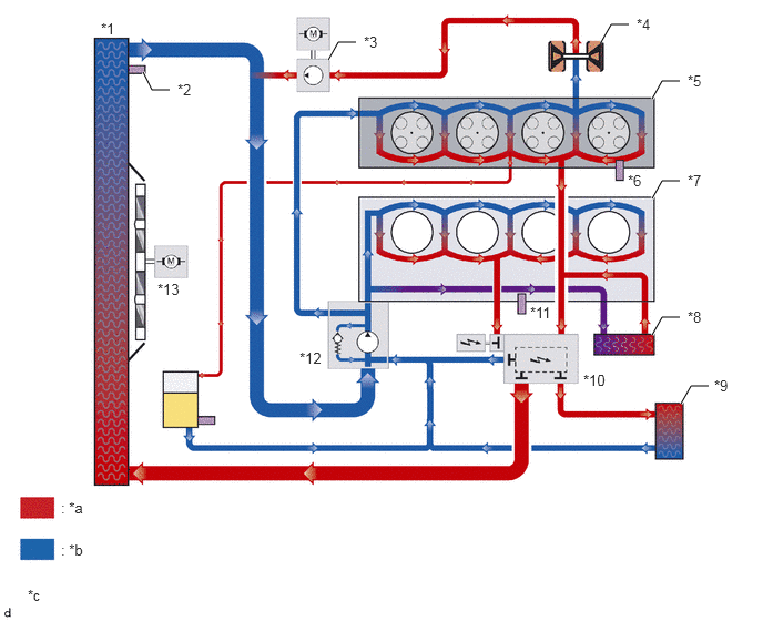
Maximum cooling is requested

·

The connection with the radiator assembly is fully open, and the electric split cooling valve opens to deliver maximum cooling efficiency.
W142987C01
6.125,3.146 6.219,2.979 6.219,2.979 6.385,2.979 true 6.396,3.792 6.49,3.625 6.49,3.625 6.656,3.625 true 1.344,0.677 1.427,0.844 1.427,0.844 1.594,0.844 true 6.125,1.865 6.219,1.698 6.219,1.698 6.385,1.698 true 6.125,0.927 6.219,0.76 6.219,0.76 6.385,0.76 true 5.646,0.396 5.74,0.229 5.74,0.229 5.906,0.229 true 3.083,0.563 3.177,0.396 3.177,0.396 3.344,0.396 true 0.948,0.188 1.26,0.344 0.313,0.156 10 false *1 1.667,0.76 1.979,0.917 0.313,0.156 10 false *2 3.417,0.313 3.729,0.469 0.313,0.156 10 false *3 5.979,0.146 6.292,0.302 0.313,0.156 10 false *4 6.458,0.677 6.771,0.833 0.313,0.156 10 false *5 5.896,1.615 6.208,1.771 0.313,0.156 10 false *6 6.458,1.615 6.771,1.771 0.313,0.156 10 false *7 6.458,2.896 6.771,3.052 0.313,0.156 10 false *8 6.708,3.542 7.021,3.698 0.313,0.156 10 false *9 5.479,3.49 5.948,3.646 0.469,0.156 10 false *10 1.479,2.635 1.948,2.792 0.469,0.156 10 false *13 0.573,4.688 0.885,4.844 0.313,0.156 10 false : *a 0.573,5.083 0.885,5.24 0.313,0.156 10 false : *b 0.26,5.51 0.573,5.667 0.313,0.156 10 false *c 2.813,3.281 3.281,3.438 0.469,0.156 10 false *12 4.979,2.854 5.448,3.01 0.469,0.156 10 false *11
*1 Radiator Assembly *2 Engine Coolant Temperature Sensor (for Radiator)
*3 Water Pump Assembly (for Turbocharger) *4 Turbocharger
*5 Cylinder Head Sub-assembly *6 Engine Coolant Temperature Sensor (for Engine)
*7 Cylinder Block *8 Oil Cooler Assembly
*9 Heater Radiator Unit Sub-assembly *10 Heat Management Module (Water Valve)
·

Electric Split Cooling Valve


*11 Oil Temperature Sensor *12 Water Inlet Housing with Water Pump Sub-assembly
*13 Fan with Motor Assembly - -
*a High Temperature Coolant *b Low Temperature Coolant
*c The illustrations shown are examples only. - -