B48 ENGINE CONTROL SFI SYSTEM DETAILS INTAKE MASS AIR FLOW METER
CONSTRUCTION
The intake mass air flow meter sub-assembly has been adopted to detect the intake air flow mass.
The intake mass air flow meter sub-assembly has a split flow path. Centrifugal force separates the clean air from moisture and particulates. In one flow path the clean air destined for measurement is conducted to the monitoring element, and the other flow path discharges moisture and particles.
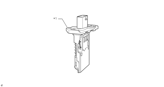
| *1 | Intake Mass Air Flow Meter Sub-assembly | - | - |
OPERATION
In the intake mass air flow meter sub-assembly, additional heat is taken away from a heated sensor element through the transfer of heat from the heating element to the air flow. The greater the air mass that flows past, the greater the amount of heat removed. The temperature difference created, which is recorded by 2 temperature sensors positioned symmetrically around the heated zone, can be used as a measured value for the air mass flowing past.
The intake mass air flow meter sub-assembly emits a frequency-coded output signal to the ECM. A low frequency indicates a low air mass and a high frequency indicates a high air mass.
Using the characteristic curve stored in the ECM, the frequency signal is converted into an air mass. The intake mass air flow meter sub-assembly is designed in such a way, via the characteristic curve range and the dynamics, that return flows (dynamic pulsation in the intake pipe) can be detected and processed both with regard to their amount (the absolute value) and direction of flow.