HEATING / AIR CONDITIONING AIR CONDITIONING SYSTEM DETAILS SERVO MOTOR
CONSTRUCTION
Air Distribution Flap Motor (No. 1 Air Conditioning Radiator Damper Servo Sub-assembly)
The air distribution flap motor (No. 1 air conditioning radiator damper servo sub-assembly) has the task of setting the air distribution via central kinematics over a cam disc.
The following air distribution flap motors (No. 1 air conditioning radiator damper servo sub-assembly) have been installed as a result of the left-right separation of the air conditioning:
Air distribution flap motor LH (No. 1 air conditioning radiator damper servo sub-assembly)
Air distribution flap motor RH (No. 1 air conditioning radiator damper servo sub-assembly)
The following air distribution programs are separately available for selection on the driver side and passenger side using the air distribution selector wheels:
Windows, upper body and footwell
Upper body and footwell
Footwell
Windows and footwell
Windows
Windows and upper body
Upper body
If the blower vent select switches in the air conditioning control assembly are used to adjust the desired air distribution, the air conditioning amplifier assembly activates the corresponding air distribution flap motor (No. 1 air conditioning radiator damper servo sub-assembly).
The cam disc is connected to the air distribution flap motor (No. 1 air conditioning radiator damper servo sub-assembly) and adjusts the air distribution flaps via the central kinematics.
The air distribution flap motor (No. 1 air conditioning radiator damper servo sub-assembly) consists basically of the following parts:
Air distribution flap motor (actuator)
Electronic module (with integrated circuit)
Transmission
Housing
The air distribution flap motor (No. 1 air conditioning radiator damper servo sub-assembly) is controlled via the LIN bus by the air conditioning amplifier assembly, and supplied with voltage and ground. In the idle state, the air conditioning amplifier assembly switches the supply voltage off.
The air distribution flap motor (No. 1 air conditioning radiator damper servo sub-assembly) includes an integrated circuit. This circuit controls the coil of the air distribution flap motor (No. 1 air conditioning radiator damper servo sub-assembly). This circuit has bus and diagnosis capabilities. After activation of the air distribution flap motor (No. 1 air conditioning radiator damper servo sub-assembly), the integrated circuit sends position feedback (actual position) to the air conditioning amplifier assembly.
After the engine is stopped and a specified waiting period (stored in the memory module of the air conditioning amplifier assembly) has elapsed, the air distribution flap motor (No. 1 air conditioning radiator damper servo sub-assembly) is moved to a predetermined stopping position. After the ignition is turned back on, the air distribution flap motor (No. 1 air conditioning radiator damper servo sub-assembly) returns to the position it was in when the engine was stopped.
Deactivation in the event of blocking
The integrated circuit detects blocking of the air distribution flap motor (No. 1 air conditioning radiator damper servo sub-assembly) by detecting increased current consumption within the adjustment range. The integrated circuit reports the fault via the LIN bus to the air conditioning amplifier assembly. The air conditioning amplifier assembly no longer activates the faulty air distribution flap motor (No. 1 air conditioning radiator damper servo sub-assembly). If blocking occurs outside of the adjusting range, an end stop is correctly detected.
Reference run
The air distribution flap motor (No. 1 air conditioning radiator damper servo sub-assembly) is unable to detect the current position (actual position). The air distribution flap motor (No. 1 air conditioning radiator damper servo sub-assembly) always moves relative to an end position of the air distribution flap (reference point). One of the end positions of the air distribution flap (closed or fully opened) serves as the reference point.
The air distribution flap is moved to an end position after replacement of the air conditioning amplifier assembly and after an interruption in the voltage supply. The end position is selected in such a way that the subsequent nominal position can be reached by the shortest path. The reference run can also be triggered by the diagnostic system.
Two cams of different widths are provided on the cam disc to allow the cam disc to be unambiguously positioned. When the microswitch for the air distribution moves over a cam, this leads to a change in state of the microswitch.
The air conditioning amplifier assembly monitors and evaluates the status of the microswitch (contact open or closed). This status information is the feedback for the position of the air distribution flap motor (No. 1 air conditioning radiator damper servo sub-assembly) or cam disc.
This mechanism achieves reliable and rapid positioning of the cam disc.
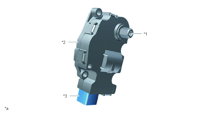
| *1 | Gear Unit Output Shaft | *2 | Air Distribution Flap Motor (No. 1 Air Conditioning Radiator Damper Servo Sub-assembly) |
| *3 | 4-pin Plug Connection | - | - |
| *a | Illustration shows a representative example. | - | - |
Mixing Flap Motor (No. 1 Air Conditioning Radiator Damper Servo Sub-assembly)
The mixing flap is used to set the air stratification. This means that the proportions of cold and warm air in the air flow to the front ventilation outlets are altered in relation to one another.
The mixing flap motor (No. 1 air conditioning radiator damper servo sub-assembly) consists basically of the following parts:
Mixing flap motor (actuator)
Electronic module (with integrated circuit)
Transmission
Housing
The air conditioning amplifier assembly evaluates the information from the mixing controller. Based on this information, the air conditioning amplifier assembly activates the mixing flap motor (No. 1 air conditioning radiator damper servo sub-assembly) via the LIN bus.
The mixing flap motor (No. 1 air conditioning radiator damper servo sub-assembly) includes an integrated circuit. This circuit has bus and diagnosis capabilities. After activation of the mixing flap motor (No. 1 air conditioning radiator damper servo sub-assembly), the integrated circuit sends position feedback (actual position) to the air conditioning amplifier assembly.
After the engine is stopped and a specified waiting period (stored in the memory module of the air conditioning amplifier assembly) has elapsed, the mixing flap motor (No. 1 air conditioning radiator damper servo sub-assembly) is moved to a predetermined stopping position. After the ignition is turned back on, the mixing flap motor (No. 1 air conditioning radiator damper servo sub-assembly) returns to the position it was in when the engine was stopped.
Deactivation in the event of blocking
The integrated circuit detects blocking of the mixing flap motor (No. 1 air conditioning radiator damper servo sub-assembly) by detecting increased current consumption within the adjustment range. The integrated circuit reports the fault via the LIN bus to the air conditioning amplifier assembly. The air conditioning amplifier assembly no longer activates the faulty mixing flap motor (No. 1 air conditioning radiator damper servo sub-assembly). If blocking occurs outside of the adjusting range, an end stop is correctly detected.
Reference run
The mixing flap motor (No. 1 air conditioning radiator damper servo sub-assembly) is unable to detect the current position (actual position). The mixing flap motor (No. 1 air conditioning radiator damper servo sub-assembly) always moves relative to an end position of the mixing flap (reference point). One of the end positions of the mixing flap (closed or fully opened) serves as the reference point.
The mixing flap is moved to an end position after replacement of the air conditioning amplifier assembly and after an interruption in the voltage supply. The end position is selected in such a way that the subsequent nominal position can be reached by the shortest path. The reference run can also be triggered by the diagnostic system.
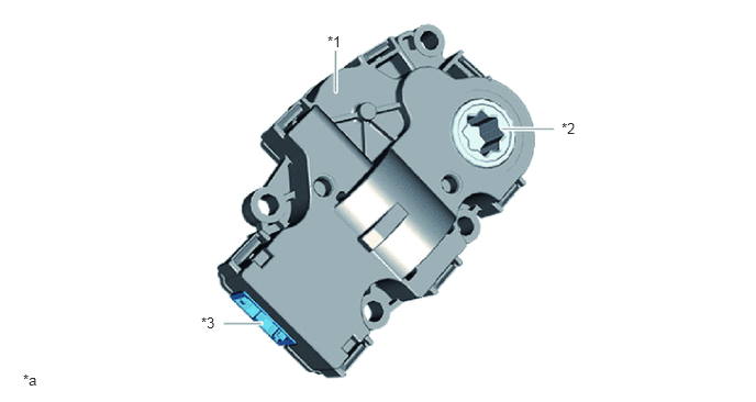
| *1 | Mixing Flap Motor (No. 1 Air Conditioning Radiator Damper Servo Sub-assembly) | *2 | Output Side |
| *3 | 4-pin Plug Connection | - | - |
| *a | Illustration shows a representative example. | - | - |
Fresh Air/Recirculated Air Flap Motor (No. 1 Air Conditioning Radiator Damper Servo Sub-assembly)
The fresh air/recirculated air flap motor (No. 1 air conditioning radiator damper servo sub-assembly) simultaneously adjusts the fresh air flap and the recirculated air flap. Both flaps are connected to each other by a cam disc.
The fresh air flap controls the proportion of fresh air in the vehicle interior. The recirculated air flap controls the air recirculation function. In the recirculated air mode, in the event of a high pollutant load, e.g. in a traffic jam, the intake of fresh air can be stopped. The air in the passenger compartment is continuously recirculated.
The fresh air/recirculated air flap motor (No. 1 air conditioning radiator damper servo sub-assembly) consists basically of the following parts:
Fresh air/recirculated air flap motor (actuator)
Electronic module (with integrated circuit)
Transmission
Housing
The air conditioning amplifier assembly evaluates the information from the air conditioning control assembly. Based on this signal, the air conditioning amplifier assembly activates the fresh air/recirculated air flap motor (No. 1 air conditioning radiator damper servo sub-assembly) via the LIN data bus.
The fresh air/recirculated air flap motor (No. 1 air conditioning radiator damper servo sub-assembly) includes an integrated circuit. This circuit has bus and diagnosis capabilities. After activation of the fresh air/recirculated air flap motor (No. 1 air conditioning radiator damper servo sub-assembly), the integrated circuit sends position feedback (actual position) to the air conditioning amplifier assembly.
After the engine is stopped and a specified waiting period (stored in the memory module of the air conditioning amplifier assembly) has elapsed, the fresh air/recirculated air flap motor (No. 1 air conditioning radiator damper servo sub-assembly) is moved to a predetermined stopping position. After the ignition is turned back on, the fresh air/recirculated air flap motor (No. 1 air conditioning radiator damper servo sub-assembly) returns to the position it was in when the engine was stopped.
Deactivation in the event of blocking
The integrated circuit detects blocking of the fresh air/recirculated air flap motor (No. 1 air conditioning radiator damper servo sub-assembly) by detecting increased current consumption within the adjustment range. The integrated circuit reports the fault via the LIN bus to the air conditioning amplifier assembly. The air conditioning amplifier assembly no longer activates the faulty fresh air/recirculated air flap motor (No. 1 air conditioning radiator damper servo sub-assembly). If blocking occurs outside of the adjusting range, an end stop is correctly detected.
Reference run
The fresh air/recirculated air flap motor (No. 1 air conditioning radiator damper servo sub-assembly) is unable to detect the current position (actual position). The fresh air/recirculated air flap motor (No. 1 air conditioning radiator damper servo sub-assembly) always moves relative to an end position of the fresh air flap or recirculated air flap (reference point). One of the end positions of the fresh air flap or the recirculated air flap (closed or fully opened) serves as the reference point.
The fresh air flap or the recirculated air flap is moved to an end position after replacement of the air conditioning amplifier assembly and after an interruption in the voltage supply. The end position is selected in such a way that the subsequent nominal position can be reached by the shortest path. The reference run can also be triggered by the diagnostic system.
| *1 | Fresh Air/Recirculated Air Flap Motor (No. 1 Air Conditioning Radiator Damper Servo Sub-assembly) | *2 | Output Side |
| *3 | 4-pin Plug Connection | - | - |
| *a | Illustration shows a representative example. | - | - |
Defroster Flap Motor (No. 1 Air Conditioning Radiator Damper Servo Sub-assembly)
The defroster flap motor (No. 1 air conditioning radiator damper servo sub-assembly) drives the defroster flaps. The two coupled defroster flaps are used to adjust the amount of air flowing to the windows.
The defroster flap motor (No. 1 air conditioning radiator damper servo sub-assembly) consists basically of the following parts:
Defroster flap motor (actuator)
Electronic module (with integrated circuit)
Transmission
Housing
The defroster flap motor (No. 1 air conditioning radiator damper servo sub-assembly) is controlled via the LIN bus by the air conditioning amplifier assembly, and supplied with voltage and ground. In the idle state, the air conditioning amplifier assembly switches the supply voltage off.
The defroster flap motor (No. 1 air conditioning radiator damper servo sub-assembly) includes an integrated circuit. This circuit has bus and diagnosis capabilities. After activation of the defroster flap motor (No. 1 air conditioning radiator damper servo sub-assembly), the integrated circuit sends position feedback (actual position) to the air conditioning amplifier assembly.
After the engine is stopped and a specified waiting period (stored in the memory module of the air conditioning amplifier assembly) has elapsed, the defroster flap motor (No. 1 air conditioning radiator damper servo sub-assembly) is moved to a predetermined stopping position. After the ignition is turned back on, the defroster flap motor (No. 1 air conditioning radiator damper servo sub-assembly) returns to the position it was in when the engine was stopped.
Deactivation in the event of blocking
The integrated circuit detects blocking of the defroster flap motor (No. 1 air conditioning radiator damper servo sub-assembly) by detecting increased current consumption within the adjustment range. The integrated circuit reports the fault via the LIN bus to the air conditioning amplifier assembly. The air conditioning amplifier assembly no longer activates the faulty defroster flap motor (No. 1 air conditioning radiator damper servo sub-assembly). If blocking occurs outside of the adjusting range, an end stop is correctly detected.
Reference run
The defroster flap motor (No. 1 air conditioning radiator damper servo sub-assembly) is unable to detect the current position (actual position). The defroster flap motor (No. 1 air conditioning radiator damper servo sub-assembly) always moves relative to an end position of a defroster flap (reference point). One of the end positions of the defroster flap (closed or fully opened) serves as the reference point.
The defroster flap is moved to an end position after replacement of the air conditioning amplifier assembly and after an interruption in the voltage supply. The end position is selected in such a way that the subsequent nominal position can be reached by the shortest path. The reference run can also be triggered by the diagnostic system.
| *1 | Defroster Flap Motor (No. 1 Air Conditioning Radiator Damper Servo Sub-assembly) | *2 | Output Side |
| *3 | 4-pin Plug Connection | - | - |
| *a | Illustration shows a representative example. | - | - |