NM3650E
_51
Engine / Hybrid System
_081556
B58 INTAKE / EXHAUST
_0398573
INTAKE SYSTEM
GE
GENERAL
F
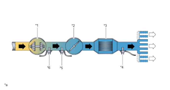
B58 INTAKE / EXHAUST INTAKE SYSTEM GENERAL SYSTEM DIAGRAM
Flow of Intake Air
1.49,0.99 1.802,1.146
0.313,0.156
10
false
*1
3.021,1 3.333,1.156
0.313,0.156
10
false
*2
4.375,1 4.688,1.156
0.313,0.156
10
false
*3
5.073,2.76 5.385,2.917
0.313,0.156
10
false
*4
2.521,2.792 2.833,2.948
0.313,0.156
10
false
*5
1.99,2.781 2.302,2.938
0.313,0.156
10
false
*6
0.188,3.51 0.5,3.667
0.313,0.156
10
false
*a
| *1 | Exhaust Manifold
·
Turbocharger Sub-assembly |
*2 | Throttle Body with Motor Assembly |
| *3 | Intake Manifold
·
Intercooler |
*4 | Vacuum Sensor Assembly |
| *5 | Intake Air Temperature Sensor | *6 | Air Pressure Sensor |
| *a | The illustrations shown are examples only. | - | - |

|
Intake Air Flow | 
|
to Cylinder |
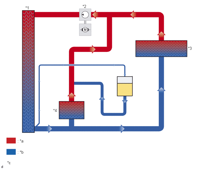
Intercooler Cooling System (Low Temperature Coolant Circuit)
0.875,0.188 1.188,0.344
0.313,0.156
10
false
*1
2.844,0.135 3.156,0.292
0.313,0.156
10
false
*2
6.479,1.583 6.792,1.74
0.313,0.156
10
false
*3
1.833,3.729 2.146,3.885
0.313,0.156
10
false
*4
0.25,5.531 0.563,5.688
0.313,0.156
10
false
*c
0.604,4.781 0.917,4.938
0.313,0.156
10
false
: *a
0.604,5.167 0.917,5.323
0.313,0.156
10
false
: *b
| *1 | Radiator Assembly | *2 | Water Pump Sub-assembly (for Low Temperature Circuit) |
| *3 | Intake Manifold
·
Intercooler |
*4 | Cooler Condenser Assembly |
| *a | High Temperature Coolant | *b | Low Temperature Coolant |
| *c | The illustrations shown are examples only. | - | - |