DRIVE SHAFT / PROPELLER SHAFT PROPELLER SHAFT ASSEMBLY REASSEMBLY
PROCEDURE

 1.INSTALL CENTER NO. 1 SUPPORT BEARING
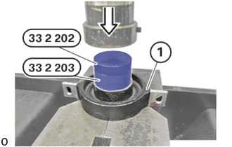
Coat the rubber-coated bearing seat of the center No. 1 support (1) using Assembly aid.
Press in the grooved a new center No. 1 support bearing using the special tools 0 492 262 (33 2 202) and 0 492 263 (33 3 203) into the center No. 1 support.
- SST
- 09300-WA160
37230
2.INSTALL CENTER NO. 1 SUPPORT BEARING ASSEMBLY
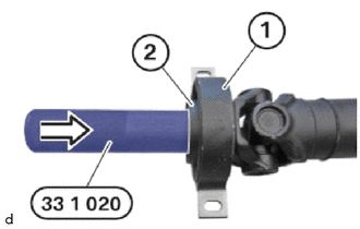
Push the center No. 1 support bearing assembly (1) onto the rear propeller shaft.
Collar (2) must point towards the rear propeller shaft assembly in the direction of travel.
Push on the center No. 1 support bearing assembly (1) up to limit position with the special tool 0 492 074 (33 1 020).
- SST
- 09500-WA200
37334D
3.INSTALL REAR PROPELLER SHAFT BOOT
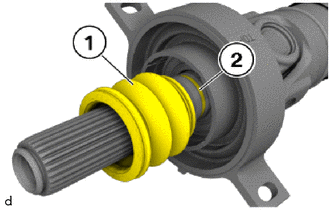
Push in the rear propeller shaft boot (1) onto the groove (2) and make sure it is securely positioned.
Coat the longitudinal splines of the rear propeller shaft assembly with center bearing with Lubricant Olistamoly 2 LN 584 LO.
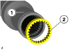
Replace the clamping ring (2).
Install the clamping ring (2) in the rear propeller shaft assembly (1).
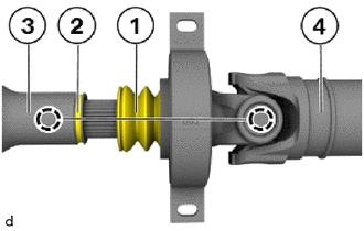
Push the front propeller shaft assembly (3) onto the longitudinal splines of the rear propeller shaft assembly (4) as per the individually applied marks.
- HINT:
-
The marks must be aligned.
Push in the rear propeller shaft boot (1) onto the groove (2) and make sure it is securely positioned.
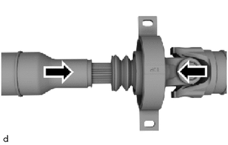
Push the front and rear propeller shaft assemblies together in the directions of the arrows.
4.INSTALL PROPELLER SHAFT SPLINE SLEEVE
for Front Side:
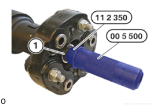
Propeller shaft spline sleeve (1) into the propeller shaft assembly using the special tools 0 490 873 (11 2 350) and 0 490 475 (00 5 500) (observe protrusion).
- SST
- 09200-WA260
09500-WA070
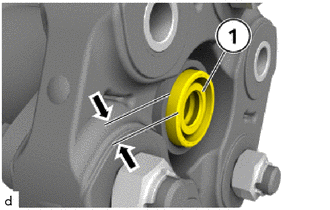
Make sure that the protrusion (arrows) of the propeller shaft spline sleeve (1) is correct.
- Centering protrusion:
4 to 6 mm (0.1575 to 0.2362 in.)
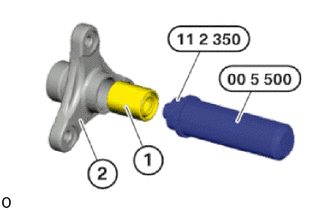
for B58 Rear Side:
Propeller shaft spline sleeve (1) into the propeller shaft assembly using the special tools 0 490 873 (11 2 350) and 0 490 475 (00 5 500) (observe protrusion).
- SST
- 09200-WA260
09500-WA070
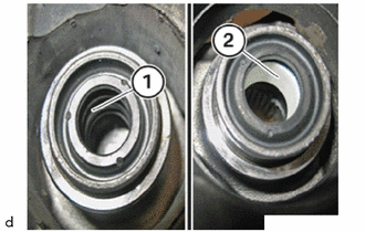
Apply a thin coat of Lubricant Olistamoly 2 LN 584 LO to the soft centering (1), if necessary.
- NOTICE:
-
Do not grease the hard centering (2).
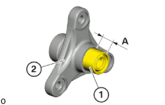
Propeller shaft spline sleeve (1) in the rear of the three-hole flange for the propeller shaft assembly into the three-hole flange (2) until the distance fits.
- Centering protrusion:
17.8 mm (0.701 in.)
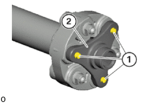
Install the three-hole frange (2)
Tighten the E16 bolts (1).
- Torque:
- 55 N*m (561 kgf*cm, 41 ft.*lbf)
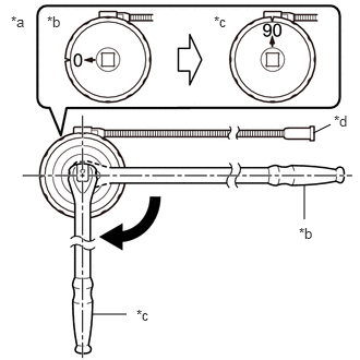
Tighten the E16 bolts (4) an additional 90°.
- SST
- 09900-WA010
- NOTICE:
-
Jointing torque and angle of rotation must be observed without fail.
- HINT:
- ·
 2.99,1.271 3.156,1.188 false 2.906,2.094 2.906,1.76 false 0.875,3 1.208,3 false 0.104,0.125 0.417,0.281 0.313,0.156 10 false *a 0.448,0.125 0.76,0.281 0.313,0.156 10 false *b 2.042,0.125 2.354,0.281 0.313,0.156 10 false *c 3.188,1.073 3.427,1.271 0.24,0.198 10 false *d 2.854,2.146 3.167,2.302 0.313,0.156 10 false *b 1.302,2.927 1.615,3.083 0.313,0.156 10 false *c
*a Example *b Before Tightening *c After Tightening *d Magnetic Portion
·The magnetic portion is used to secure the gauge to the vehicle.
·After first adjusting the needle of the gauge to 0°, tighten to the specified angle.
·Perform the work procedure carefully so that the gauge, etc. does not become tilted.